
Installation Guide, Fifth Edition - HP 9000 rp8420 Server


Chapter 1
Introduction
Overview
17
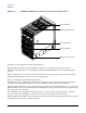
Front Panel
Front Panel Indicators and Controls
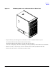
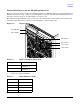
The front panel, located on the front of the server, includes the power switch and status LEDs. See Figure 1-4.
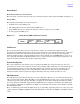
Status LEDs
The following status LEDs are on the front panel:
• Standby Power status LED (green)
• MP (Management Processor) Present status LED (green)
• Status LEDs: Run (green), Fault (red), Attention (yellow), and Power (green) LEDs
• Remote port status LED (green)
Figure 1-4 Front Panel LEDs and Power Switch
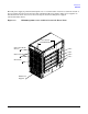
Cell Board
The cell board contains the processors, main memory, and the cell controller (CC) application-specific
integrated circuit (ASIC) that interfaces the processors and memory to the I/O. The CC provides a connection
that allows communication with other cell boards in the system. It connects to the processor-dependent
hardware (PDH) and micro controller hardware. Each cell board holds up to 16 DIMMS. There can be one to
four cell boards installed in an HP 9000 rp8420 server. A cell board can be selectively powered down for cell
replacement without affecting cells in other configured partitions.
System Backplane
The server backplane board contains a pair of crossbar chips (XBC), the clock generation logic, the reset
generation logic, some power regulators, and two local bus adapter (LBA) chips that create internal PCI buses
for communicating with the core I/O cards. The backplane also contains connectors for attaching the cell
boards, PCI-X backplane, MP core I/O cards, SCSI cables, bulk power, chassis fans, front panel display,
intrusion switches, external system bus adaptor (SBA) link connectors, and the system scan card.
I/O Subsystem
All of the I/O is integrated into the system by way of the PCI busses. The CC on each cell board communicates
with one system bus adapter (SBA). The SBA converts the SBA link protocol into “ropes.” A rope is defined as
a high-speed, point-to-point data bus. The SBA can support up to 16 of these high-speed bi-directional links
for a total aggregate bandwidth of approximately 4GB/s. The server supports a maximum of two SBAs with
the capability of supporting an additional two SBAs in an externally connected I/O cabinet known as the HP
Server Expansion Unit.
There are LBA chips on the PCI-X backplane that act as a bus bridge, supporting either one or two ropes and
capable of driving 33 MHz or 66 MHz for PCI cards. The LBAs can also drive at 66 MHz or 133 MHz for PCI-X
cards.
RUN
Fault
Attention Remote
MP Present
Standby Power
Power
Power
Switch