
HP 9000 rp8420 Server - User Service Guide, Fifth Edition


7. If removed, replace the DIMM cover and tighten all the captive screws.
8. Replace the cell board in the cabinet.
9. Use the MP:CM> PE option C to return 48V power to the cell board
10. Use the MP:CM> bo option to boot the partition.
Removing and Replacing a Voltage Regulator Module
There are a total of 15 voltage regulator modules (VRMs) located on the cell board. Both
low-voltage VRMs and high-voltage VRMs reside on the cell board.
Physical Identification for a VRM There are three methods to visually determine if a VRM is a
low- or high-voltage VRM:
Markings Low-voltage VRMs are marked “0.88–1.9V” while high-voltage VRMs are marked
“1.75–3.3V.”
Key Pin Low-voltage VRMs have the key pin located near the center of the connector while
high-voltage VRMs have the key pin near the edge of the connector.
Heatsink Low-voltage VRMs have a smaller heatsink while high-voltage VRMs have a larger
heatsink.
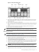
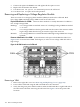
Firmware Identification for a VRM System firmware will report which VRM has failed. Use
Figure 6-40 to locate the failed VRM. In the figure, LV refers to low voltage while HV refers to
high voltage.
Figure 6-40 VRM Locations on Cell Board
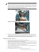
Removing a VRM
1. Remove the right side cover. See “Removing and Replacing Covers” (page 104).
2. Power off the cell board using the MP command menu PE command.
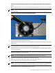
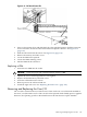
3. Verify that the green power LED located on either the left-hand side or right-hand side of
the cell board is off before removing the cell board. See Figure 6-41 for the power LED
locations.
148 Removal and Replacement