
HP 9000 rp8420 Server - User Service Guide, Fifth Edition
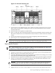
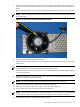

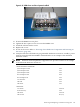

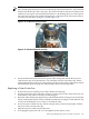
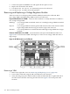
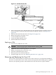
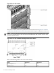

Figure 6-36 VRM Cover and Door Opener Installed
17. Position the DIMM cover in place.
18. Tighten the four captive screws to secure the DIMM cover.
19. Install the cell board in the server.
20. Replace the covers.
21. Power on the server. Refer to “Powering down Hardware Components and Powering on
the Server” (page 103).
22. Verify the firmware and hardware programmable hardware revisions in “standby” power
mode by using the MP:CM>SYSREV command. Below is an example of the minimum
firmware version.
NOTE: Firmware must be updated to support the new processors. Below is an example
of the minimum Firmware Version 3.1.
PROGRAMMABLE HARDWARE
1.002System Backplane GPM
1.002System Backplane FM
1.002System Backplane OSP
2.000PCI-X Backplane LPM
1.000PCI-X Backplane HS
2.008Core IO Master
1.002Cell LPM
1.007Cell PDHC
FIRMWARE:
A.006.012Core IO MP
1.008Event Dictionary
A.003.023Cell PDHC
22.2 (PA)Cell Pri SFW
Removing and Replacing a Central Processing Unit 145