
HP 9000 rp8420 Server - User Service Guide, Fifth Edition

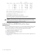
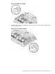
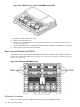
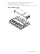
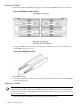
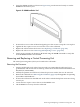
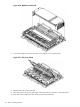

Figure 6-24 VRM Cover, Door Opener and DIMM Cover Installed
4. Install the cell board into the server.
5. Replace the right side cover.
6. Power on the server. Refer to “Powering down Hardware Components and Powering on
the Server” (page 103).
7. Power up the nPartition. See Appendix E ‘Operating System Boot and Shutdown’ for details.
8. Verify proper operation of the cell board.
Removing and Replacing DIMMs
The dual in-line memory modules (DIMMs) reside on the cell board. The cell power must be
turned off to replace this FRU. See “Powering down Hardware Components and Powering on
the Server” (page 103).
Figure 6-25 Cell Board with DIMM Location
Preliminary Procedures
These procedures must be completed before removing the DIMM assembly.
136 Removal and Replacement