
HP 9000 rp8420 Server - User Service Guide, Fifth Edition


5-3 PCI Power Supply LED Locations.................................................................................................84
5-4 Fan LED Locations........................................................................................................................85
5-5 Cell Board LED Locations.............................................................................................................86
5-6 PCI OL* LED Locations.................................................................................................................87
5-7 Core I/O Card Bulkhead LEDs......................................................................................................88
5-8 Core I/O Button Location..............................................................................................................89
5-9 Disk Drive LED Location..............................................................................................................90
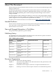
5-10 Temperature States........................................................................................................................93
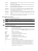
5-11 Firmware Update Command Example.........................................................................................97
5-12 HP 9000 rp8420 server Cabinet FRUs (Front View)......................................................................98
5-13 HP 9000 rp8420 server Cabinet FRUs (Rear View).......................................................................99
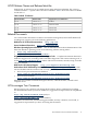
5-14 de Command Output..................................................................................................................100
6-1 Cover Locations ..........................................................................................................................105
6-2 Top Cover Removed ...................................................................................................................106
6-3 Side Cover Removal Detail..........................................................................................................107
6-4 HP 9000 rp8420 server Bezel Removal and Replacement...........................................................108
6-5 Front Panel Assembly Location ..................................................................................................109
6-6 Front Panel Board Detail.............................................................................................................110
6-7 Front Panel Board Cable Location on Backplane........................................................................111
6-8 Front Smart Fan Assembly Location ..........................................................................................111
6-9 Front Fan Removal ......................................................................................................................112
6-10 Rear Smart Fan Assembly Location ............................................................................................113
6-11 Rear Fan Detail............................................................................................................................113
6-12 Disk Drive Location ....................................................................................................................114
6-13 Disk Drive Detail ........................................................................................................................115
6-14 Removable Media Drive Location ..............................................................................................116
6-15 Removable Media Drive Detail...................................................................................................116
6-16 Cell Board Extraction Lever.........................................................................................................117
6-17 Cell Board Power LED.................................................................................................................118
6-18 Extraction Lever...........................................................................................................................119
6-19 Cell Board Removal and Replacement .......................................................................................119
6-20 Extraction Lever...........................................................................................................................120
6-21 de Command Output..................................................................................................................121
6-22 VRM Cover Installed ..................................................................................................................135
6-23 Door Opener Installed ................................................................................................................135
6-24 VRM Cover, Door Opener and DIMM Cover Installed .............................................................136
6-25 Cell Board with DIMM Location.................................................................................................136
6-26 DIMM Cover Assembly...............................................................................................................137
6-27 DIMM Detail with Locations.......................................................................................................138
6-28 DIMM Removal Tools..................................................................................................................138
6-29 DIMM Installation Tool...............................................................................................................139
6-30 DIMM Cover Removed...............................................................................................................140
6-31 CPU Cover Raised.......................................................................................................................140
6-32 CPUs with Turbocooler Fans.......................................................................................................141
6-33 ZIF Socket Lock/Unlock Peep Hole Location..............................................................................143
6-34 VRM Cover Installed ..................................................................................................................144
6-35 Door Opener Installed ................................................................................................................144
6-36 VRM Cover and Door Opener Installed .....................................................................................145
6-37 Heatsink with Turbo-Cooler Fan Removed................................................................................146
6-38 Soldered Heatsink and Clip........................................................................................................147
6-39 Machined Heatsink and Clip.......................................................................................................147
6-40 VRM Locations on Cell Board.....................................................................................................148
6-41 Cell Board Power LED.................................................................................................................149
6-42 Core I/O Location .......................................................................................................................150
6-43 Core I/O Card Bottom with DIP Switch Location Shown...........................................................150
11