
Installation Guide, Fifth Edition - HP 9000 rp8420 Server

Chapter 2
Installation
Cabling and Power Up
58
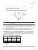
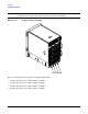
IMPORTANT The minimum supported N+1 BPS configuration for one cell board must have BPS slots 0, 1,
and 3 populated. When selecting a single power source, the power cords are connected into A0
and A1.
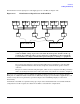
NOTE Label the AC power cords during the installation. One suggestion is to use tie wraps that have
the flag molded into the tie wrap. The flag can be labeled using the appropriate two characters
to represent the particular AC power input (for example, A0). Another suggestion would be to
use color-coded plastic bands. Use one color to represent the first pair A0/A1 and another color
to represent the second pair B0/B1 (provided a second power source is available at the customer
site).
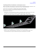
Applying Power to the HP 9000 rp8420 server
Observe the functionality of the server before attaching any LAN or serial cables, the system console, or any
peripherals to the server. Then, after applying an active AC power source to the server, make the following
observations at three different intervals, or points in time.
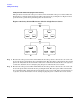
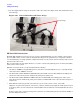
INTERVAL ONE
The power has just been applied to the server but the front panel On/Off switch is Off. The front air intake
fans will flash a dim red color, the BPS will flash amber and an amber light is present on the hard disk drives.
INTERVAL TWO
After the power has been plugged into the server for about 30 seconds, the standby power turns on and the
front intake fan LED indicators turn solid green. The BPS will flash green and the amber light is still present
on the hard disk drives. The front panel On/Off switch is Off at this interval. Housekeeping power is up at
this point.
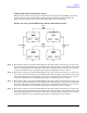
INTERVAL THREE
With the On/Off switch on the front of the server set to On, the intake fans spin up and become noticeably
audible while the LED indicator remains solid green. The BPS LED indicator turns a solid green and the PCI
backplane power supply LED indicators turn solid green. The hard disk drive LED turns green briefly and
then the LED turns off.
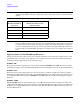
Table 2-4 BPS to Cell Board Configuration to Achieve N+1
Number of Cell
Boards Installed in
the Server
Number of Operational BPS
Installed to Achieve N+1
Functionality
13
24
35
46