
HP 9000 rp8420 Server - User Service Guide, Fifth Edition
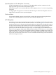
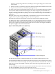

Figure 1-11 PCI-X Board to Cell Board Block Diagram
The HP 9000 rp8420 server supports two internal SBAs. The SBAs generate 32 rope buses (16 per
SBA). The 32 available internal rope buses are divided in the following manner:
• Two ropes are routed as single rope bundles to support the core I/O boards through LBAs
located on the core I/O backplane.
• Two ropes are routed as single rope bundles to two LBAs to support two slots for PCI and
PCI-X cards.
• Twenty-eight ropes are bundled in two rope pairs to 14 LBAs to support 14 slots for PCI
and PCI-X cards.
NOTE: PCI-X slots 1–7 are dual rope slots while slot 8 is a single rope slot. A rope is defined
as a high-speed, point-to-point data bus.
The PCI-X backplane is the primary I/O interface for HP 9000 rp8420 server systems. It provides
16 64-bit, hot-plug PCI/PCI-X slots. Fourteen of the slots have dual ropes connected to the LBA
chips. The remaining two slots have a single rope connected to each LBA chip. Each of the 16
slots is capable of 66MHz/33MHz PCI or 133MHz/66MHz PCI-X. All 16 PCI slots are keyed for
3.3 V connectors (accepting both Universal and 3.3 V cards). The PCI-X backplane does not
provide any 5 V slots for the I/O cards.
The PCI-X backplane is physically one board but behaves like two independent partitions. SBA
0 and its associated LBAs and eight PCI-X slots form one I/O partition. SBA 1 and its associated
LBAs and eight PCI-X slots form the other I/O partition. One I/O partition can be powered down
separate from the other I/O partition.
32 Introduction