
HP 9000 rp8420 Server - User Service Guide, Fifth Edition
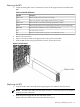
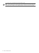


unit. Twelve 120-mm fans housed in cosmetic plastic fan carriers and mounted externally to the
rear chassis wall pull air through the unit.
Each fan is controlled by a smart fan control board embedded in the fan module plastic housing.
The smart fan control board receives fan control input from the system fan controller on the
system backplane and returns fan status information to the system fan controller. The smart fan
control board also controls the power and the pulse width modulated control signal to the fan
and monitors the speed indicator back from the fan. The fan status LED is driven by the smart
fan control board.
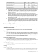
Bulk Power Supply Cooling
Cooling for the bulk power supplies (BPS) is provided by two 60-mm fans contained within each
BPS. Air flows into the front of the BPS and is exhausted out of the top of the power supply
though upward facing vents near the rear of the supply. The air is then ducted out of the rear of
the chassis.
PCI/Mass Storage Section Cooling
Six 92-mm fans located between the mass storage devices and the PCI card cage provide airflow
through these devices. The PCI fans are powered off of housekeeping power and run at full
speed at all times. The air is pulled through the mass storage devices and pushed through the
PCI card cage. Separation is provided between the PCI bulkheads to allow adequate exhaust
ventilation and to help reduce the localized airflow dead spots that typically occur at the faceplate
tail of each PCI card.
Standby Cooling
Several components within the chassis consume significant amounts of power while the system
is in standby mode. The system fans will run at a portion of full speed during standby to remove
the resulting heat from the cabinet. The fans within the power supply will operate at full speed
during standby.
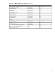
Typical Power Dissipation and Cooling
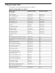
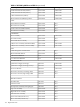
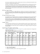
Table B-5 “Typical HP 9000 rp8420 server Configurations” provides calculations for configurations
as described in the table.
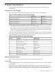
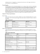
Table B-5 Typical HP 9000 rp8420 server Configurations
Typical CoolingTypical
Power
Bulk Power
Supplies
Core
I/O
Hard Disk
Drives
DVDsPCI Cards
(assumes 10W
each)
Memory per
Cell Board
Cell
Board
BTU/hourWattsQtyQtyQtyQtyQtyGBytesQty
121543560624216164
10720314062421684
975428576220844
74602185424216162
617618094220882
597517504220842
387111343110841
The air-conditioning data in Table B-5 is derived using the following equations.
• Watts x (0.860) = kcal/hour
• Watts x (3.414) = Btu/hour
• Btu/hour divided by 12,000 = tons of refrigeration required
180 System Specifications