
HP 9000 rp8420 Server - User Service Guide, Fifth Edition
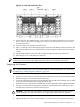
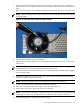
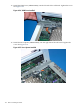
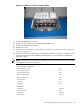
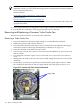
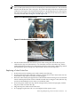
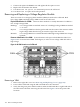
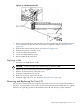
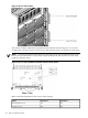

Figure 6-32 CPUs with Turbocooler Fans
11. Loosen the four T15 VRM heat-sink screws and the four turbocooler load screws. Loosen
these screws in an X pattern, turning each screw 2–3 turns until all four screws are loose
from the cell board.
12. Push the load screw sequencer toward the fan.
13. Place a 2.5 mm hex driver through the peep hole between the blades in the fan and turn the
ZIF socket lock/unlock screw one half turn counter-clockwise to unlock the CPU from the
socket.
14. Lift the CPU/Turbocooler/Power Pod assembly straight up and off the cell board.
15. Place the pin cover on the bottom of the CPU.
NOTE: If the socket will not be populated with a replacement processor module, place the ZIF
socket cover over the ZIF socket. Tighten the four screws in an X pattern until secure.
Replacing the Processor
TIP: When installing CPU 0, you can remove VRM 4 for ease of installation. See “Removing
and Replacing a Voltage Regulator Module” (page 148).
1. Remove the ZIF socket cover from the cell board.
2. Using a 2.5 mm hex driver, turn the ZIF socket lock/unlock screw to the unlocked position.
3. Remove the pin cover from the bottom of the CPU.
4. Lower the CPU/Turbocooler/Power Pod assembly onto the ZIF socket making sure it is held
level to the board until the pins engage the ZIF socket.
5. Push the load screw sequencer toward the fan to expose the peep hole through the fan blades.
6. Using a 2.5 mm hex driver through the peep hole, turn the ZIF socket lock/unlock screw
one half turn clockwise to lock the CPU into place.
CAUTION: Do not exceed one half turn clockwise when locking the CPU into the ZIF
socket. Damage to the ZIF socket will occur, requiring the cell board to be replaced.
7. Push the load screw sequencer away from the fan.
8. Tighten the four T15 screws on the sequencer 2–3 turns each in an X pattern until secure.
Removing and Replacing a Central Processing Unit 141