
HP 9000 rp8420 Server - User Service Guide, Fifth Edition
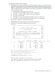
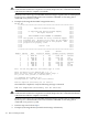
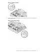
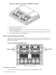
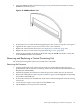
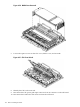

Figure 6-30 DIMM Cover Removed
7. Loosen the captive screws on the CPU cover, lift the cover, and set aside.
Figure 6-31 CPU Cover Raised
8. Identify the CPUs to be removed.
9. Disconnect the CPU power pod input connector from its connector on the cell board.
10. Disconnect the Turbocooler fan connector from the cell board.
140 Removal and Replacement