
Switch 7700 Configuration Guide, v2

RIP 75
Display and Debug RIP After configuring RIP, execute the display command in all views to display the RIP
configuration, and to verify the effect of the configuration. Execute the
debugging command in user view to debug the RIP module. Execute the reset
command in RIP view to reset the ssytem configuratio parameters of RIP.
Example: Typical RIP
Configuration
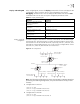
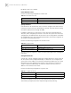
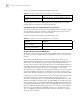
As shown in Figure 4, the Switch C connects to the subnet 117.102.0.0 through
the Ethernet port. The Ethernet ports of Switch A and Switch B are connected to
the network 155.10.1.0 and 196.38.165.0, respectively. Switch C, Switch A, and
Switch B are connected by Ethernet 110.11.2.0. Correctly configure RIP to ensure
that Switch C, Switch A, and Switch B can interconnect.
Figure 4 RIP Configuration
Note: The following configuration only shows the operations related to RIP. Before
performing the following configuration, verify that the Ethernet link layer works
normally.
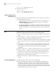
1 Configure RIP on Switch A:
[Switch A] rip
[Switch A-rip] network 110.11.2.0
[Switch A-rip] network 155.10.1.0
2 Configure RIP on Switch B:
[Switch B] rip
[Switch B-rip] network 196.38.165.0
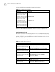
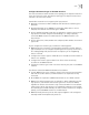
Table 21 Display and Debug RIP
Operation Command
Display the current RIP running
state and configuration
information.
display rip
Enable the RIP debugging
information
debugging rip packets
Enable the debugging of RIP
receiving packet.
debugging rip receive
Enable the debugging of RIP
sending packet.
debugging rip send
Restore the default RIP settings reset
Network address:
155.10.1.0/24
Interface address:
155.10.1.1/24
Switch A
Interface address:
110.11.2.1/24
Ethernet
Switch C
Network address:
110.11.2.2/24
Switch B
Network address:
196.38.165.0/24
Interface address:
196.38.165.1/24
Interface address:
117.102.0.1/16
Network address:
117.102.0.0/16