
Switch 7700 Configuration Guide, v2

66 CHAPTER 5: ROUTING PROTOCOL OPERATION
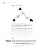
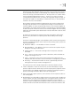
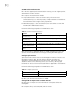
Figure 3 Static Route Configuration
1 Configure the static route for Ethernet Switch A:
[Switch A] ip route-static 1.1.3.0 255.255.255.0 1.1.2.2
[Switch A] ip route-static 1.1.4.0 255.255.255.0 1.1.2.2
[Switch A] ip route-static 1.1.5.0 255.255.255.0 1.1.2.2
2 Configure the static route for Ethernet Switch B:
[Switch B] ip route-static 1.1.2.0 255.255.255.0 1.1.3.1
[Switch B] ip route-static 1.1.5.0 255.255.255.0 1.1.3.1
[Switch B] ip route-static 1.1.1.0 255.255.255.0 1.1.3.1
3 Configure the static route for Ethernet Switch C:
[Switch C] ip route-static 1.1.1.0 255.255.255.0 1.1.2.1
[Switch C] ip route-static 1.1.4.0 255.255.255.0 1.1.3.2
4 Configure the default gateway of the Host A to be 1.1.1.2
5 Configure the default gateway of the Host B to be 1.1.5.2
6 Configure the default gateway of the Host C to be 1.1.4.1
Using this procedure, all the hosts or switches in Figure 3 can be interconnected in
pairs.
Static Route Fault
Diagnosis and
Troubleshooting
The Switch 7700 is not configured with the dynamic routing protocol, and both
the physical status and the link layer protocol status of the interface is enabled,
but the IP packets cannot be forwarded normally.
■ Use the display ip routing-table protocol static command to view
whether the corresponding static route is correctly configured.
■ Use the display ip routing-table command to view whether the
corresponding route is valid.
A
B
C
Host 1.1.1.1
Host 1.1.4.2
Host 1.1.5.1
Switch A
Switch B
Switch C
1.1.1.2/24
1.1.2.1/24
1.1.5.2/24
1.1.3.1/24
1.1.3.2/24
1.1.4.1/24