
Switch 7700 Configuration Guide, v2

14 CHAPTER 11: SYSTEM MANAGEMENT
Set backboard view
The backboard view command determines the backplane bandwidth allocated to
each slot in the Switch 7700. Currently, the Switch Fabric has the capability of
32Gbpos full duplex yet the chassis has a maximum capability of 48 Gbps full
duplex. This command sets the bandwidth available to each slot in the system.
Perform the following configuration in system view.
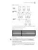
[SW7700]set backboard view INTEGER<0-5>
MOD1 MOD2 MOD3 MOD4 MOD5 MOD6
0: 8G, 8G, 8G, 8G
1: 8G, 8G, 4G, 4G, 4G, 4G
2: 8G, 8G, 8G, 4G, 4G
3: 8G, 8G, 8G, 6G, 2G
4: 8G, 8G, 6G, 6G, 2G, 2G
5: 8G, 8G, 6G, 4G, 4G, 2G
The default setting is 1 (8G to slots 1 and 2, 4G to slots 3-6)
Display and Debug
Device Management
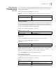
After the above configuration, execute display command in all views to display
the device management configuration, and verify the effect of the configuration.
System Maintenance
and Debugging
This section includes descriptions of the following types of system maintenance ad
debugging:
■ Configuring System Basics
■ Display the State and Information of the System
■ System Debugging
Configuring System
Basics
This section describes the following basic system configuration tasks:
■ Setting the System Name
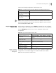
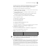
Tab le 26 Set Back Board View
Operation Command
Set back board view set backboard view value
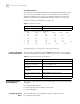
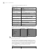
Tab le 27 Display and Debug Device Management
Operation Command
Display the set back board view. display backboard view
Display the module types and
running states of each card.
display device [ detail | [ shelf shelf-no ] [ frame
frame-no ] [ slot slot-no ] ]
Display the running state of the
built-in fans.
display fan [fan-id]
Display the information about the
environment.
display environment
Display the used status of switch
memory.
display memory [ slot slot-number ]
Display the state of the power. display power [ power-ID ]