
Switch 7700 Configuration Guide, v2

140 CHAPTER 5: ROUTING PROTOCOL OPERATION
[Switch C] interface Vlan-interface 3
[Switch C-Vlan-interface3] ip address 193.1.1.2 255.255.255.0
[Switch C] interface vlan-interface 5
[Switch C-Vlan-interface5] ip address 195.1.1.2 255.255.255.0
[Switch C] ospf
[Switch C-ospf] area 0
[Switch C-ospf-area-0.0.0.0] network 193.1.1.0 0.0.0.255
[Switch C-ospf-area-0.0.0.0] network 195.1.1.0 0.0.0.255
[Switch C] bgp 200
[Switch C-bgp] peer 193.1.1.1 as-number 100
[Switch C-bgp] peer 195.1.1.1 as-number 200
4 Configure Switch D:
[Switch D] interface vlan-interface 4
[Switch D-Vlan-interface4] ip address 194.1.1.1 255.255.255.0
[Switch D] interface vlan-interface 5
[Switch D-Vlan-interface5] ip address 195.1.1.1 255.255.255.0
[Switch D] ospf
[Switch D-ospf] area 0
[Switch D-ospf-area-0.0.0.0] network 194.1.1.0 0.0.0.255
[Switch D-ospf-area-0.0.0.0] network 195.1.1.0 0.0.0.255
[Switch D-ospf-area-0.0.0.0] network 4.0.0.0 0.255.255.255
[Switch D] bgp 200
[Switch D-bgp] peer 195.1.1.2 as-number 200
[Switch D-bgp] peer 194.1.1.2 as-number 200
To enable the configuration, all BGP neighbors will be reset using reset bgp all
command.
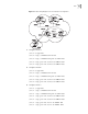
After above configuration, due to the fact that the MED attribute of route 1.0.0.0
discovered by Switch C is less than that of Switch B, Switch D will first select the
route 1.0.0.0 from Switch C.
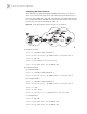
If the MED attribute of Switch A is not configured, the local preference on Switch
C is configured as follows:
5 Configure the local preference attribute of Switch C:
■ Add ACL 1 on Switch C and permit network 1.0.0.0
[Switch C] acl number 1