
Switch 7700 Configuration Guide, v2

138 CHAPTER 5: ROUTING PROTOCOL OPERATION
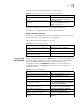
Using the display bgp routing-table command ,you can view the BGP routing
table on Switch D. Note: Switch D also knows the existence of network 1.0.0.0.
<Switch D> display bgp routing-table
Flags: # - valid, ^ - best,
D - damped, H - history,
I - internal, S aggregate suppressed
Dest/Mask Pref Next-Hop Med Local-Pref
Origin As-Path
*> 1.0.0.0/8 192.1.1.1 0 IGP
100
Configuring BGP Routing
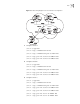
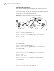
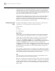
This example illustrates how the administrators manage the routing by BGP
attributes. All Ethernet switches are configured with BGP, and IGP in AS 200
utilizes OSPF. Switch A is in AS 100, and acts as Switch B of AS 200 and BGP
neighbor of Switch C. Both Switch B and Switch C operates IBGP to Switch D.
Switch D is also in AS 200.
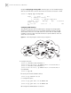
Figure 15 Networking Diagram of BGP Routing Configuration
1 Configure Switch A:
[Switch A] interface Vlan-interface 2
[Switch A-Vlan-interface2] ip address 192.1.1.1 255.255.255.0
[Switch A] interface Vlan-interface 3
[Switch A-Vlan-interface3] ip address 193.1.1.1 255.255.255.0
a Enable BGP
[Switch A] bgp 100
b Specify the network that BGP sends to
[Switch A-bgp] network 1.0.0.0
c Configure the peers
[Switch A-bgp] peer 192.1.1.2 as-number 200
[Switch A-bgp] peer 193.1.1.2 as-number 200
d Configure the MED attribute of Switch A