
Switch 7700 Configuration Guide, v2

BGP 137
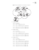
3 Configure Switch C:
a Configure VLAN 3:
[Switch C] interface Vlan-interface 3
[Switch C-Vlan-interface3] ip address 193.1.1.1 255.255.255.0
b Configure VLAN 4:
[Switch C] interface vlan-Interface 4
[Switch C-Vlan-interface4] ip address 194.1.1.1 255.255.255.0
[Switch C] ospf
[Switch C-ospf] area 0
[Switch C-ospf-area-0.0.0.0] network 194.1.1.0 0.0.0.255
c Configure BGP peers and route reflector:
[Switch C] bgp 200
[Switch C-bgp] peer 193.1.1.2 as-number 200
[Switch C-bgp] peer 193.1.1.2 reflect-client
[Switch C-bgp] peer 194.1.1.2 as-number 200
[Switch C-bgp] peer 194.1.1.2 reflect-client
4 Configure Switch D:
a Configure VLAN 4:
[Switch D] interface vlan-interface 4
[Switch D-Vlan-interface4] ip address 194.1.1.2 255.255.255.0
[Switch D] ospf
[Switch D-ospf] area 0
[Switch D-ospf-area-0.0.0.0] network 194.1.1.0 0.0.0.255
b # Configure BGP peers
[Switch D] bgp 200
[Switch D-bgp] peer 194.1.1.1 as-number 200
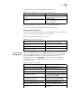
Using the display bgp routing-table command, you can view BGP routing table
on Switch B. Note: Switch B has known the existence of network 1.0.0.0.
<Switch B> display bgp routing-table
Flags: # - valid, ^ - best,
D - damped, H - history,
I - internal, S aggregate suppressed
Dest/Mask Pref Next-Hop Med Local-Pref
Origin As-Path
*> 1.0.0.0/8 192.1.1.1 0 IGP
100