
Switch 7700 Configuration Guide, v2

136 CHAPTER 5: ROUTING PROTOCOL OPERATION
Configuring BGP Route Reflector
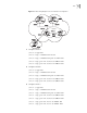
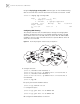
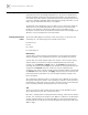
Switch B receives an update packet passing EBGP and transmits it to Switch C.
Switch C is a reflector with two clients: Switch B and Switch D. When Switch C
receives a route update from Switch B, it will transmit such information to Switch
D. It is required to establish an IBGP connection between Switch B and Switch D,
because Switch C reflects information to Switch D.
Figure 14 Networking Diagram of BGP Route Reflector Configuration
1 Configure Switch A:
[Switch A] interface vlan-interface 2
[Switch A-Vlan-interface2] ip address 192.1.1.1 255.255.255.0
[Switch A] bgp 100
[Switch A-bgp] network 1.0.0.0 255.0.0.0
[Switch A-bgp] peer 192.1.1.2 as-number 200
2 Configure Switch B:
a Configure VLAN 2:
[Switch B] interface Vlan-interface 2
[Switch B-Vlan-interface2] ip address 192.1.1.2 255.255.255.0
b Configure VLAN 3:
[Switch B] interface Vlan-interface 3
[Switch B-Vlan-interface3] ip address 193.1.1.2 255.255.255.0
[Switch B] ospf
[Switch B-ospf] area 0
[Switch B-ospf-area-0.0.0.0] network 193.1.1.0 0.0.0.255
c Configure peers.
[Switch B] bgp 200
[Switch B-bgp] peer 192.1.1.1 as-number 100
[Switch B-bgp] peer 193.1.1.1 as-number 200