
Switch 7700 Configuration Guide, v2

OSPF 95
Example: OSPF
Configuration
Configuring DR Election Based on OSPF Priority
In this example, four Switch 7700 routers, Switch A, Switch B, Switch C, and
Switch D, which can perform the router functions and run OSPF, are located on
the same segment, as shown in
Figure 6.
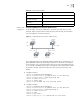
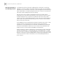
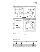
Figure 6 Configuring DR Election Based on OSPF Priority
The commands listed in the following examples enable Switch A and Switch C to
be DR and BDR respectively. The priority of Switch A is 100, which is the highest
on the network, so it is elected as the DR. Switch C has the second highest priority,
so it is elected as the BDR. The priority of Switch B is 0, which means that it cannot
be elected as the DR. and Switch D does not have a priority, which takes 1 by
default.
1 Configure Switch A:
[Switch A] interface Vlan-interface 1
[Switch A-Vlan-interface1] ip address 196.1.1.1 255.255.255.0
[Switch A-Vlan-interface1] ospf dr-priority 100
[Switch A] router id 1.1.1.1
[Switch A] router ospf
[Switch A-ospf] network 196.1.1.0 0.0.0.255 area 0
2 Configure Switch B:
[Switch B] interface Vlan-interface 1
[Switch B-Vlan-interface1] ip address 196.1.1.2 255.255.255.0
[Switch B-Vlan-interface1] ospf dr-priority 0
[Switch B] router id 2.2.2.2
[Switch B] ospf
[Switch B-ospf] area 0
[Switch B-ospf-area-0.0.0.0] network 196.1.1.0 0.0.0.255
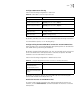
Display OSPF retransmission
list
display ospf retrans-queue
Display the information of
OSPF ABR and ASBR
display ospf abr-asbr
Display OSPF interface
information
display ospf interface
Display OSPF errors display ospf error
Table 50 Display and Debug OSPF
Operation Command
Switch A
1.1.1.1
DR
Switch D
Switch B
Switch C
4.4.4.4
2.2.2.2
3.3.3.3
BDR
196.1.1.4/24
196.1.1.3/24196.1.1.2/24
196.1.1.1/24