
HP StorageWorks 4x00/6x00/8x00 Enterprise Virtual Array hardware configuration guide (5697-7338, February 2008)


0172b
1
2
2
3
4
5
6
7
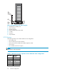
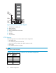
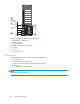
Figure 32 EVA4x00 2C3D cab l e diagram
1. HSV200-A/B controller pair
2. Drive enclosure
3. Bottom terminator
4. Dual controller interconnect cable
5. Ycable
6. ID port 6
7. Top terminator
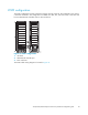
2C3D features
The follow ing features
are included with the 2C3D configuration:
• One storage rack
• Three 14–drive bay FC drive enclosures
• One 2–port enclosure a
ddress bus s helf ID expansion cable
• Six AC strips
• Two 1U PDUs (not shown in figure)
NOTE:
Disks must be ordered s
eparately.
Table 13 Maximum storage capacities for the 2C3D configuration
Disk Size
Maximum
Capacit y
72 GB 3.0 TB
146 GB 6.1 TB
250 GB 10.5 TB
300 GB 12.6 TB
500 GB 21.0 TB
48
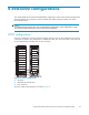
EVA4x00 configurations