
3X-KZPEA Release Notes, March 2005


CHA
ID7
J5 out
J3 in
w/Black
Plug
w/Black
Plug
AlphaServer 1
ES45
Y-Cable
SCSI Cable SCSI Cable
CHB
ID7
Ext.
Term
KZPEA
CHA
ID6
J5 out
J3 in
AlphaServer 2
ES45
Y-Cable
CHB
ID7
KZPEA
CHA
Dual Channel
I/O Module
Storage
Enclosure
DS-SL13R-BA
CHB
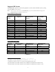
Figure 1 Configuration A KZPEA, Shared SCSI Bus
Configuration B
Configuration B (Figure 2) requires the use of a Tri-link at the middle node, use of a terminator cable
between the middle and end node with one adapter being in the middle of the bus. The on-board termination
of both adapters in both nodes must be disabled for each channel used in a shared bus configuration.
Termination is disabled by removing jumper J5 for SCSI Channel 1/A and jumper J3 for SCSI Channel 2/B,
and also setting the Host Adapter SCSI Termination to “Low OFF/High OFF” for Channel 1/A and
“Disabled” for Channel 2/B with the SCSI Configuration Utility.
Refer to the KZPEA User’s Guide regarding operation of the adapter’s onboard SCSI Configuration Utility.
Note: For shared bus configuration only, please disregard the “SCSI Termination” paragraph under
section 2.1.2 of the KZPEA User Guide which states that the adapter can only be located at the end
of the bus, requiring jumpers J3 and J5 to be installed.
Termination will be supplied by the storage enclosure at one end of the bus and by a terminator cable at the other
end of the bus.
Note: When configuring the KZPEA in a shared SCSI bus configuration which will contain a boot, cluster,
quorum, or dump disk, you must connect the shared cable to Channel A of the KZPEA adapters on both
nodes if using an SRM Console Revision less than V6.6. Console Revisions of V6.6 and greater do not
have this restriction.
Required Components for Shared SCSI Bus Support (per shared bus) for Configuration B
2-5-2 P/N Qty. Description
3X-H8411-AA 1 Shared SCSI adapter kit (
12-44100-03 Tri-link and 2
Connector Plugs P/N: 12-10015-01)
3X-BN56A-03 A/R 3M TERM SCSI CABLE
3X-BN56A-04 A/R 4M TERM SCSI CABLE
9