
HP StorageWorks 4x00/6x00/8x00 Enterprise Virtual Array hardware configuration guide (5697-7338, February 2008)


0112a
Front
Rear
1
2
3
4
56 78 9
10
10
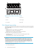
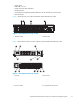
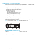
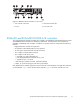
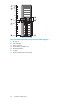
Figure 1 FC drive enclosure—front and rear views
1. Drive bay 1 2. Drive bay 14
3. EMU
4. I/O module B
5. Blower 1 6. Power supply 1
7. Blower 2 8. P ower supply 2
9. I/O module A
10. Status indicators (EMU, enclosure power,
enclosure fault)
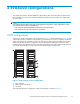
Fibre Channel loop switches
The Enterprise Virtual Array uses FC loop switches to connect all of the drive enclosures to the controller
pair via copper cables. Each FC loop switch acts as a central point of interconnection and establishes a
physical loop topology.
Switch use:
• EVA4000/4100 does not use switches on any configuration
• EVA6000/6100 uses switches on all configurations
• EVA8000/81 0 0 only uses switches with more than four disk enclosures
The storage system uses one of the following loop switches:
• 30-10022-01 loop switch—used with 2 Gb and 4 Gb controllers (required on EVA
4100/6100/8100)
• 30-10010-02 loop switch—used with 2 Gb and 4 Gb controllers
CAUTION:
When using the 30-10022-01 loop switch, ensure that there is no disk in bays 12, 13, and 14 in
enclosures 17, 20, and 24. Slots 13 and 14 are assigned the same ALPA as the controllers and slot
12 is assigned ALPA 4, which is taken by the 30-10022-01 loop switch. Failure to adhere to this rule
will disrupt storage system operation. HP also recommends that you keep three additional bays open
to ma intain the maximum device c ount of 120. For ease of use and consistency in configurations, HP
recommends keeping bays 12, 1 3, and 14 open in enclosures 16 and 19.
The major features of the FC loop switch are:
• 2.125 Gbps operating speed
14
EVA 4x00/6x00/8x00 hardware