
HP StorageWorks disk enclosure midplane replacement instructions (533480-001, March 2009)

DescriptionDrive LED
• Flashing blue—Used to locate drive.
• Solid amber—Drive fault.
Bi-color (top)
Table 2 I/O module and system fan LEDs
DescriptionItem
= Unit identification. Flashing blue LED
that is remotely activated by an application
client.
nl
nl
= Enclosure external health. Solid green
indicates normal operation of the link module.
Flashing green indicates power up. An off
condition may indicate a firmware malfunction.
nl
nl
= Enclosure fault warning. Flashing amber
indicates a fault of lesser importance, while solid
amber indicates a fault of greater importance
(a component needs to be replaced).
I/O module LED
Green = Normal operation.
nl
nl
Amber = Fault condition.
nl
nl
Off = Fan unseated from connector or failed.
System fan LED
Removing the midplane
1. Power down the array. For the EVA, use HP Command View EVA
or, on the EVA4400 only, the Web-based operator control panel
(WOCP). Powering down the controllers also removes power from
the disk enclosures. To power down with HP Command View EVA:
a. In the HP Command View EVA navigation tree, select your
storage system.
b. Select the Shut down button.
c. On the Shutdown Options pane, in the Power the Whole System
OFF section, set a value of up to 60 minutes to delay the power
down of the array (if desired). Click the Power OFF button.
2. Remove the Fibre Channel, Ethernet, and power cables from the
enclosure components. Ensure all cabling is marked so as to facilitate
reconnecting later.
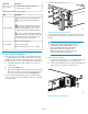
3. Pull off the left and right bezel ears (1, Figure 1).
1
2
Figure 1 Removing enclosure from rack
4. Loosen the front panel thumbscrews (2) that secure the enclosure
faceplate to the front of the rack, and remove the enclosure from
the rack.
WARNING!
A disk enclosure fully populated with disk drives is
heavy. Remove the disks and place them on a clean
surface, preferably stacked in the order removed,
before removing the enclosure from the rack.
Otherwise, two people are required to remove the
enclosure from the rack to prevent injury.
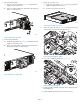
5. Remove both power supplies.
a. Move the latch to the left (1, Figure 2), grasp the handle, and
pull the power supply slightly out of the enclosure (2).
b. Position one hand under the power supply, and with the other
hand, pull the power supply out of the enclosure.
1
2
15800
Figure 2 Removing a power supply
Page 2