
HP 3PAR T-Class Installation and Deinstallation Guide


6 Understanding LED Status
Using the Component LEDs
HP 3PAR T-Class Storage System components have LEDs to indicate the hardware is properly
functioning and to help identify errors. These LEDs help diagnose basic hardware problems.
You can quickly identify hardware problems by examining the LEDs on all the components. Use
the tables and diagrams in the following sections to verify the hardware is properly functioning.
Removing the Bezels and Unlocking the Door
WARNING! Hazardous energy is located behind the rear access door of the storage system
cabinet. Use caution when working with the door open.
NOTE: If your 3PAR cabinet has locking fascias, first remove the fascias to access the system
bezel. See “Storage System Fascias” (page 46).
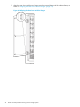
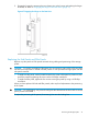
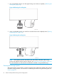
• To view the node, drive chassis or service processor LEDs, remove the bezels.
• To view the power supply, battery or PDU LEDs, open the rear door by unlatching the three
latches of the door (T800 systems contain PDUs in the front and rear of the cabinet).
NOTE: Many LEDs are visible without removing the bezels. To view the power supply, battery
or PDU LEDs, open the rear door of the cabinet.
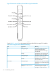
Drive Cage LEDs
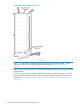
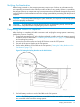
The T-Class system uses a DC4 drive chassis that holds one DC4 drive cage housing two drive
cage FC-AL modules and a maximum of 10 drive magazines. See Figure 71 (page 79).
Figure 71 DC4 Drive Cage
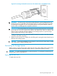
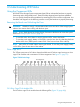
DC4 Drive Cage FC-AL Module LEDs
The DC4 drive cage FC-AL modules have the following LEDs (Figure 72 (page 80)):
Using the Component LEDs 79