
HP 3PAR T-Class Installation and Deinstallation Guide


1. Access the rear of the system and verify all power supplies are set to the OFF position.
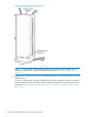
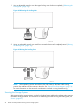
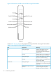
2. Verify the safety breakers on all four of the PDUs are set to the OFF position, as shown in
“Setting the Safety Breakers to the OFF Position” (page 71).
Figure 63 Setting the Safety Breakers to the OFF Position
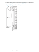
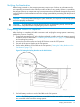
3. For a T400 or drive expansion cabinet, at the front of the cabinet, use #2 Phillips screwdriver
to remove the screws securing the 4U filler panel covering the lowest chassis bay in the cabinet,
then remove the panel. For T800 node cabinets, remove both side panels to access the main
AC cords.
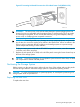
4. Locate the main power cord for each of the four PDUs. Remove the protective packaging from
the power receptacle connectors.
NOTE: For T800 storage system, remove the cabinet side panels to gain access to the four
PDU power cords.
NOTE: If a cabinet does not have components installed in the top four bays (bays 0–3, or
the highest 16U of the cabinet), it is not necessary to connect the two upper PDUs (PDU 0 and
PDU 1). Use the two upper PDUs for future upgrades.
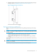
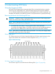
5. Route the main power cords through the lower access opening at the bottom of the cabinet
or the upper access opening at the top of the cabinet. The side panels can be removed for
easier cabling access (“Routing the Main Power Cords” (page 72)).
Connecting the Main Power Cords 71