
HP 3PAR T-Class Installation and Deinstallation Guide
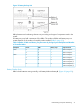
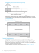
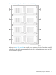
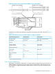
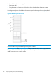
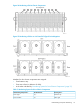
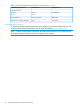
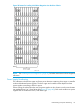
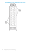

Figure 24 Control Cache and Data Cache DIMMs in the Controller Node
Numbers for controller nodes and their components are assigned in the order indicated in Table 10
(page 35).
Table 10 Numbering System for Controller Nodes and Their Components
Running from...Are Numbered...The Following Components...
left to right
1
and top to bottom0,1,2,3,4,5,6,7Controller nodes
left to right
1
0,1,2,3,4,5PCI adapters
PCI ports
top to bottom1,2dual-port adapters
top to bottom1,2,3,4quad-port adapters
Control Cache DIMMs
left to right
1
0,1
0,1,2,3,4,5,6,7
control cache
data cache
Data Cache DIMMs
top to bottom0,1Bank 0
0,1Bank 1
0,1Bank 2
1
When facing the storage system.
Drive Chassis Numbering
Depending on the specific configuration, a storage system may support up to 64 drive chassis. A
cabinet provides 10 drive bays and may support up to 10 drive chassis. Each drive chassis slot
accommodates a single drive magazine which holds four disks for a total of 40 hard drives per
drive chassis.
Understanding Component Numbering 35