
HP 3PAR T-Class Installation and Deinstallation Guide
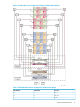

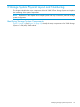
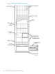
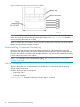
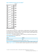

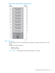
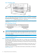

Figure 17 Numbering of PDUs
NOTE: For T800 systems, the PDUs are positioned back-to-back to only occupy two units of space
at the bottom of the cabinet instead of the standard four units of space. PDUs are accessible from
both the front and the rear of the system. “Controller Node Cabinet Component Layout by Storage
System Model
3
” (page 28) illustrates PDU placement for a T800 system.
Each PDU has two power banks with a separate circuit breaker and use only with storage system
components (Figure 18 (page 30)).
Figure 18 Power Banks in the PDU
WARNING! To avoid possible injury, damage to storage system equipment, and potential loss
of data, do not use the surplus power outlets in the storage system PDUs. Never use outlets in the
PDUs to power components not belong to the storage system or power storage system components
residing in other cabinets.
NOTE: For more information on PDUs and storage system configurations, see “Preparing for
Storage System Installation” (page 9).
Battery Backup Unit Numbering
The storage system controller node cabinet includes one or two battery trays to house the battery
backup units (BBU). A BBU supplies enough power to write the cache memory to the drive inside
the nodes in the event of a power failure. One battery per controller node is required for all storage
system configurations.
A battery tray is located directly below the storage system backplane. Storage systems with six or
eight controller nodes requires a second battery tray. The second battery tray rests immediately
above the storage system backplane.
Each battery unit contains two independently-switched batteries, labeled battery Aand battery B
(Figure 19 (page 31)).
30 Storage System Physical Layout and Numbering