
HP 3PAR T-Class Installation and Deinstallation Guide
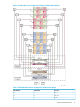
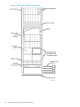
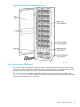
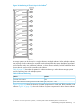

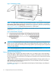

Figure 13 Placement of the Service Processor (T400)
NOTE: For T800 Storage Systems, the service processor is located above the system backplane,
below the lowest drive chassis but above the upper battery tray. Figure 15 (page 28) illustrates
service processor placement for a T800.
When a cabinet does not include a service processor, a filler panel covers the area of the cabinet
that the service processor normally occupies.
Understanding Component Numbering
Because of the large number of potential system configurations, HP standardized component
placement and internal cabling to simplify installation and maintenance. System components are
placed in the cabinet according to the principles outlined in this section and numbered according
to their order and location in the cabinet.
NOTE: For information about standardized cabling, see “Controller Node to Drive Chassis
Cabling” (page 208).
Cabinet Numbering
The 2M (40U) cabinet is an EIA-standard rack divided into 10 chassis bays (4U) for housing
storage system components.
Numbers for chassis bays are assigned:
• Beginning with 0
• From top to bottom
Figure 14 (page 27) illustrates numbering of chassis bays in a cabinet.
26 Storage System Physical Layout and Numbering