
HP 3PAR T-Class Installation and Deinstallation Guide


E Controller Node to Drive Chassis Cabling
This appendix described standard and split mode node to drive cage cabling for two and four
node systems.
For information about node numbering and drive cage numbering, see Chapter 2 (page 23).
For information about PCI cards, their installation order, and their usage, see Appendix F (page 210).
CAUTION: Do not use patch panels for connecting controller node(s) and drive chassis. Using
patch panels may cause weakening of signal integrity and possible communication failure.
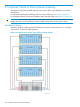
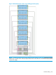
Standard Cabling
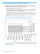
The following figures display standard cabling for two and four node systems. For six and eight
node systems, continue the cabling pattern.
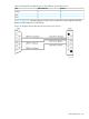
Figure 119 Standard Node to Drive Cage Cabling (2 Node System)
208 Controller Node to Drive Chassis Cabling