
HP 3PAR T-Class Installation and Deinstallation Guide
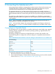
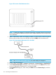
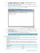
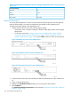
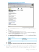
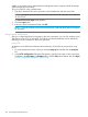
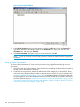
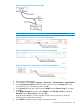
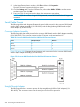

Table 27 Standard terminal emulation connection settings for maintenance PC to a service processor
(continued)
Connection Settings
8Data bits
noneParity
1Stop bits
Xon/XoffFlow Control
Ethernet Connection
To connect the maintenance PC to the service processor through the private Local Area Network
using an Ethernet cable, you must first configure the LAN settings on the maintenance PC.
To configure the LAN settings on the maintenance PC:
1. Unlock and open the rear door of the storage system cabinet.
• If necessary, insert a crossover Category 5 Ethernet cable (RJ45 to RJ45) into the proper
Ethernet port.
• For the service processor (“Wintec Service Processor Ethernet Ports” (page 194) or
“Supermicro Service Processor Ethernet Ports” (page 194) or “Supermicro II Service
Processor Ethernet Ports” (page 194)), use port ETH1 at the rear of the service processor.
Figure 105 Wintec Service Processor Ethernet Ports
Figure 106 Supermicro Service Processor Ethernet Ports
Figure 107 Supermicro II Service Processor Ethernet Ports
2. Connect the free end of the crossover Ethernet cable to the Ethernet port in the maintenance
PC.
3. Power on the maintenance PC.
4. Right-click the My Network Places desktop icon to bring up the shortcut menu.
5. Click Properties.
The Network and Dial-up Connections window appears (“Network and Dial-Up Connections
Window” (page 195)).
194 Connecting the Maintenance PC