
HP 3PAR T-Class Installation and Deinstallation Guide
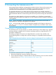
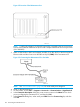
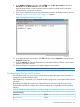
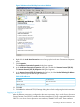
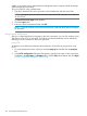
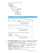
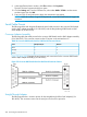

Figure 102 Location of the Maintenance Port
NOTE: A cable with adapter (P/N 180-0055) should be connected to the service processor.
Disconnect the ethernet cable from the RJ-45 to DB-9 adapter attached to the service processor
(P/N 180-0059).
3. Attach a DB9 female to RJ45 serial adapter assembly (P/N 180–0055) to the free end of the
Ethernet cable and then insert it into the DB9 serial port (COM1) of the maintenance PC.
Figure 103 Connecting the Maintenance PC to the Node
NOTE: See “Serial Cable Pinouts” (page 200) for serial cable pinout diagrams.
4. Power on the maintenance PC.
5. On the taskbar, choose Start > Programs > Accessories > Communications > HyperTerminal.
6. In the Connection Description dialog box, enter a session name in the Name box for which
you are configuring the maintenance PC, and then click OK.
7. In the Connect To dialog box, select serial port COM1 from the Connect using list, and then
click OK .
192 Connecting the Maintenance PC