HP 3PAR StoreServ 7000/7450 Storage Cabling Configuration Guide A: 2 Node Systems with Small 2.5-inch Drive Enclosures Abstract This guide provides cabling information for authorized technicians performing installation and maintenance services on the HP 3PAR StoreServ 7000/7450 Storage systems.
© Copyright 2013 Hewlett-Packard Development Company, L.P. The information contained herein is subject to change without notice. The only warranties for HP products and services are set forth in the express warranty statements accompanying such products and services. Nothing herein should be construed as constituting an additional warranty. HP shall not be liable for technical or editorial errors or omissions contained herein. Acknowledgments Microsoft®, Windows®, are U.S.
Contents 1 Cabling Preparation for HP 3PAR StoreServ 7000/7450.................................4 Following Precautions................................................................................................................4 Identifying and Labeling the Components....................................................................................4 2 Cabling HP 3PAR StoreServ 7000/7450.......................................................7 2 Node 1 Drive Enclosures (1S)..............................
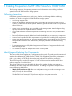
1 Cabling Preparation for HP 3PAR StoreServ 7000/7450 The following instructions list important precautions and information about cabling installation options for the HP 3PAR StoreServ Storage system.
Types of Components Use the red and green color coding to assist with the cabling. Only connect to components sharing the same color.
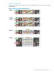
Labeling the Enclosures Before connecting the cables: • Labels (A, B, C, and D) are provided to help identify the enclosures in the storage system. Apply the labels to each enclosure in a visible location and avoid covering other labels • Apply label A to the controller enclosure with nodes 0 and 1. Alternate the labeling (A/B) on each enclosure below the controller enclosure If applicable, a system using four nodes, apply label C to the controller enclosure with nodes 2 and 3.
2 Cabling HP 3PAR StoreServ 7000/7450 The following illustrative sections provide a rear view of the rack with recommended racking configuration of the system. 2 Node 1 Drive Enclosures (1S) Before you begin cabling the storage system, carefully read or print the section, including figures 1 and 2, “Identifying and Labeling the Components” (page 4).
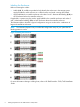
Attach DP-1 Chains to Enclosures This system does not require any connections to node port DP-1. Attach DP-2 Chains to Enclosures Red routing Connect Node 0 (DP-2) to the I/O 0 (DP-1) on the B drive enclosure closest to the controller. Green routing Connect Node 1 (DP-2)to I/O 1 on the B drive enclosure farthest from the controller. NOTE: 8 The two adjacent enclosures are not directly connected.
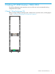
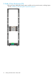
Review Completed Cabling 2 Node 1 Drive Enclosures (1S) 9
2 Node 2 Drive Enclosures (2S) Before you begin cabling the storage system, carefully read or print the section, including figures 1 and 2, “Identifying and Labeling the Components” (page 4).
Attach DP-1 Chains to Enclosures Red routing Connect Node 0 (DP-1) to the I/O 0 (DP-1) on the A drive enclosure closest to the controller. Green routing Connect Node 1 (DP-1)to I/O 1 (DP-1)on the A drive enclosure farthest from the controller. NOTE: The two adjacent enclosures are not directly connected.
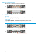
Attach DP-2 Chains to Enclosures Red routing Connect Node 0 (DP-2) to the I/O 0 (DP-1) on the B drive enclosure closest to the controller. Green routing Connect Node 1 (DP-2) to I/O 1 on the B drive enclosure farthest from the controller. NOTE: 12 The two adjacent enclosures are not directly connected.
Review Completed Cabling 2 Node 2 Drive Enclosures (2S) 13
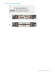
2 Node 3 Drive Enclosures (3S) Before you begin cabling the storage system, carefully read or print the section, including figures 1 and 2, “Identifying and Labeling the Components” (page 4).
Attach DP-1 Chains to Enclosures Red routing Connect Node 0 (DP-1) to the I/O 0 (DP-1) on the A drive enclosure closest to the controller. Green routing Connect Node 1 (DP-1) to I/O 1 (DP-1) on the A drive enclosure farthest from the controller. NOTE: The two adjacent enclosures are not directly connected.
Attach DP-2 Chains to Enclosures Red routing 1. Connect Node 0 (DP-2) to the I/O 0 (DP-1) on the “B” drive enclosure closest to the controller. 2. Connect all “B” drive enclosures from (DP-2) to (DP-1) working away from the controller. Green routing 1. Connect Node 1 (DP-2) to I/O 1 on the “B” drive enclosure farthest from the controller. 2. Connect all “B” drive enclosures from (DP-2) to (DP-1) working toward the controller. NOTE: 16 No two adjacent enclosures are directly connected.
Review Completed Cabling 2 Node 3 Drive Enclosures (3S) 17
2 Node 4 Drive Enclosures (4S) Before you begin cabling the storage system, carefully read or print the section, including figures 1 and 2, “Identifying and Labeling the Components” (page 4).
Attach DP-1 Chains to Enclosures Red routing 1. 2. Connect Node 0 (DP-1) to the I/O 0 (DP-1) on the A drive enclosure closest to the controller. Connect all A drive enclosures from (DP-2) to (DP-1) working away from the controller. Green routing 1. 2. Connect Node 1 (DP-1) to I/O 1 (DP-1) on the A drive enclosure farthest from the controller. Connect all A drive enclosures from (DP-2) to (DP-1) working toward the controller. NOTE: The two adjacent enclosures are not directly connected.
Attach DP-2 Chains to Enclosures Red routing 1. 2. Connect Node 0 (DP-2) to the I/O 0 (DP-1) on the B drive enclosure closest to the controller. Connect all B drive enclosures from (DP-2) to (DP-1) working away from the controller. Green routing 1. 2. Connect Node 1 (DP-2) to I/O 1 on the B drive enclosure farthest from the controller. Connect all B drive enclosures from (DP-2) to (DP-1) working toward the controller. NOTE: 20 The two adjacent enclosures are not directly connected.
Review Completed Cabling 2 Node 4 Drive Enclosures (4S) 21
2 Node 5 Drive Enclosures (5S) Before you begin cabling the storage system, carefully read or print the section, including figures 1 and 2, “Identifying and Labeling the Components” (page 4).
Attach DP-1 Chains to Enclosures Red routing 1. 2. Connect Node 0 (DP-1) to the I/O 0 (DP-1) on the A drive enclosure closest to the controller. Connect all A drive enclosures from (DP-2) to (DP-1) working away from the controller. Green routing 1. 2. Connect Node 1 (DP-1) to I/O 1 (DP-1) on the A drive enclosure farthest from the controller. Connect all A drive enclosures from (DP-2) to (DP-1) working toward the controller. NOTE: The two adjacent enclosures are not directly connected.
Attach DP-2 Chains to Enclosures Red routing 1. 2. Connect Node 0 (DP-2) to the I/O 0 (DP-1) on the B drive enclosure closest to the controller. Connect all B drive enclosures from (DP-2) to (DP-1) working away from the controller. Green routing 1. 2. Connect Node 1 (DP-2) to I/O 1 on the B drive enclosure farthest from the controller. Connect all B drive enclosures from (DP-2) to (DP-1) working toward the controller. NOTE: 24 The two adjacent enclosures are not directly connected.
Review Completed Cabling 2 Node 5 Drive Enclosures (5S) 25
2 Node 6 Drive Enclosures (6S) Before you begin cabling the storage system, carefully read or print the section, including figures 1 and 2, “Identifying and Labeling the Components” (page 4).
Attach DP-1 Chains to Enclosures Red routing 1. 2. Connect Node 0 (DP-1) to the I/O 0 (DP-1) on the A drive enclosure closest to the controller. Connect all A drive enclosures from (DP-2) to (DP-1) working away from the controller. Green routing 1. 2. Connect Node 1 (DP-1) to I/O 1 (DP-1) on the A drive enclosure farthest from the controller. Connect all A drive enclosures from (DP-2) to (DP-1) working toward the controller. NOTE: The two adjacent enclosures are not directly connected.
Attach DP-2 Chains to Enclosures Red routing 1. 2. Connect Node 0 (DP-2) to the I/O 0 (DP-1) on the B drive enclosure closest to the controller. Connect all B drive enclosures from (DP-2) to (DP-1) working away from the controller. Green routing 1. 2. Connect Node 1 (DP-2) to I/O 1 on the B drive enclosure farthest from the controller. Connect all B drive enclosures from (DP-2) to (DP-1) working toward the controller. NOTE: 28 The two adjacent enclosures are not directly connected.
Review Completed Cabling 2 Node 6 Drive Enclosures (6S) 29
2 Node 7 Drive Enclosures (7S) Before you begin cabling the storage system, carefully read or print the section, including figures 1 and 2, “Identifying and Labeling the Components” (page 4).
Attach DP-1 Chains to Enclosures Red routing 1. 2. Connect Node 0 (DP-1) to the I/O 0 (DP-1) on the A drive enclosure closest to the controller. Connect all A drive enclosures from (DP-2) to (DP-1) working away from the controller. Green routing 1. 2. Connect Node 1 (DP-1) to I/O 1 (DP-1) on the A drive enclosure farthest from the controller. Connect all A drive enclosures from (DP-2) to (DP-1) working toward the controller. NOTE: The two adjacent enclosures are not directly connected.
Attach DP-2 Chains to Enclosures Red routing 1. 2. Connect Node 0 (DP-2) to the I/O 0 (DP-1) on the B drive enclosure closest to the controller. Connect all B drive enclosures from (DP-2) to (DP-1) working away from the controller. Green routing 1. 2. Connect Node 1 (DP-2) to I/O 1 (DP-1) on the B drive enclosure farthest from the controller. Connect all B drive enclosures from (DP-2) to (DP-1) working toward the controller. NOTE: 32 The two adjacent enclosures are not directly connected.
Review Completed Cabling 2 Node 7 Drive Enclosures (7S) 33
2 Node 8 Drive Enclosures (8S) Before you begin cabling the storage system, carefully read or print the section, including figures 1 and 2, “Identifying and Labeling the Components” (page 4).
Attach DP-1 Chains to Enclosures Red routing 1. 2. Connect Node 0 (DP-1) to the I/O 0 (DP-1) on the A drive enclosure closest to the controller. Connect all A drive enclosures from (DP-2) to (DP-1) working away from the controller. Green routing 1. 2. Connect Node 1 (DP-1) to I/O 1 (DP-1) on the A drive enclosure farthest from the controller. Connect all A drive enclosures from (DP-2) to (DP-1) working toward the controller. NOTE: The two adjacent enclosures are not directly connected.
Attach DP-2 Chains to Enclosures Red routing 1. 2. Connect Node 0 (DP-2) to the I/O 0 (DP-1) on the B drive enclosure closest to the controller. Connect all B drive enclosures from (DP-2) to (DP-1) working away from the controller. Green routing 1. 2. Connect Node 1 (DP-2) to I/O 1 on the B drive enclosure farthest from the controller. Connect all B drive enclosures from (DP-2) to (DP-1) working toward the controller. NOTE: 36 The two adjacent enclosures are not directly connected.
Review Completed Cabling 2 Node 8 Drive Enclosures (8S) 37
2 Node 9 Drive Enclosures (9S) Before you begin cabling the storage system, carefully read or print the section, including figures 1 and 2, “Identifying and Labeling the Components” (page 4).
Attach DP-1 Chains to Enclosures Red routing 1. 2. Connect Node 0 (DP-1) to the I/O 0 (DP-1) on the A drive enclosure closest to the controller. Connect all A drive enclosures from (DP-2) to (DP-1) working away from the controller. Green routing 1. 2. Connect Node 1 (DP-1) to I/O 1 (DP-1) on the A drive enclosure farthest from the controller. Connect all A drive enclosures from (DP-2) to (DP-1) working toward the controller. NOTE: The two adjacent enclosures are not directly connected.
Attach DP-2 Chains to Enclosures Red routing 1. 2. Connect Node 0 (DP-2) to the I/O 0 (DP-1) on the B drive enclosure closest to the controller. Connect all B drive enclosures from (DP-2) to (DP-1) working away from the controller. Green routing 1. 2. Connect Node 1 (DP-2) to I/O 1 on the B drive enclosure farthest from the controller. Connect all B drive enclosures from (DP-2) to (DP-1) working toward the controller. NOTE: 40 The two adjacent enclosures are not directly connected.
Review Completed Cabling 2 Node 9 Drive Enclosures (9S) 41
3 Additional Resources and Related Documentation Contacting HP For worldwide technical support information, see the HP support website: http://www.hp.