
HP 3PAR F-Class, T-Class, StoreServ 10000 Storage Troubleshooting Guide (QL226-96953, May 2013)


4 Understanding T-Class Storage System LED Status
Using the T-Class Component LEDs
The T-Class Storage System components have LEDs to indicate whether or not the hardware is
functioning properly and to help identify errors. These LEDs help diagnose basic hardware problems.
You can quickly identify hardware problems by examining the LEDs on all the components and
using the following tables and illustrations in this chapter.
If you detect any problems during inspection of the LEDs, contact your Authorized Service Provider.
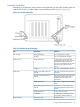
Removing the Bezels and Unlocking the Door
If your cabinet has locking fascias, you must first remove the fascias to access the system bezel.
WARNING! Hazardous energy is located behind the rear access door of the storage system
cabinet. Use caution when working with the door open.
• To view the node, drive chassis or SP LEDs, remove the bezels.
• To view the power supply, battery or PDU LEDs, open the rear door by unlatching the three
latches on the door.
NOTE: Many LEDs are visible without removing the bezels. To view the power supply, battery
or PDU LEDs, open the rear door of the cabinet.
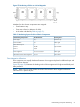
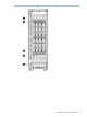
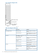
Drive Cage LEDs
The DC4 drive chassis holds one DC4 drive cage housing with two drive cage FC-AL modules and
a maximum of ten drive magazines.
Figure 61 DC4 Drive Cage
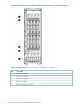
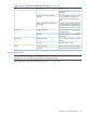
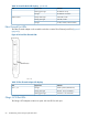
DC4 Drive Cage FC-AL Module LEDs
DC4 drive cage FC-AL modules have the following LEDs (Figure 62 (page 56)):
Using the T-Class Component LEDs 55