
HP 3PAR StoreServ Storage Concepts Guide (OS 3.1.2 MU2) (QR482-96384, June 2013)
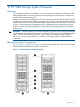
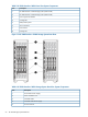
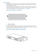
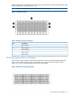
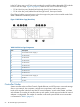
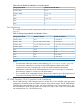
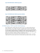
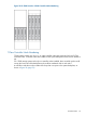

Table 9 System Models and Number of Controller Nodes
Number of Controller NodesStorage System Model
2 or 4StoreServ 7000
2, 4, 6, or 8StoreServ 10000
2 or 4T400
2, 4, 6, or 8T800
2F200
4F400
Port Numbering
The number of host ports each storage system model can accommodate is summarized in Table 10
(page 67).
Table 10 Storage System Models and Number of Ports
Number of iSCSI PortsNumber of FC PortsStorage System Model
0–4 (10 Gb/s)0–12StoreServ 7200
0–8 (10 Gb/s)0–12 (2 node); 0–24 (4 node)StoreServ 7400
0–4 (2 node); 0–8 (4 node) (10 Gb/s)4–12 (2 node); 8–24 (4 node)StoreServ 7450
0–180–288StoreServ 10000
0–160–64T400
0–320–128T800
0–8 (1 Gb/s)0–8F200
0–16 (1 Gb/s)0–16F400
NOTE:
• For information about port location and numbering, see “Port Location Formats” (page 28).
• For information about how to view the control cache DIMM and data cache DIMM
configurations for each controller node, see the HP 3PAR Command Line Interface
Administrator's Manual and HP 3PAR Management Console Online Help. For information
about memory expansion, contact your HP representative.
• For a complete list of supported third-party hardware and software, go to the Single Point of
Connectivity Knowledge (SPOCK) website http://www.hp.com/storage/spock.
HP 3PAR StoreServ 7000 Controller Node Numbering
The HP 3PAR StoreServ 7000 Storage system can contain two or four controller nodes per system
configuration. Controller nodes are located in the rear of the node enclosure. The HP 3PAR StoreServ
7200 Storage system includes two nodes, which are numbered 0 and 1 from bottom to top. The
HP 3PAR StoreServ 7400 Storage system can include two nodes or four nodes. Four-node systems
are numbered from 0 to 3 from bottom to top.
Controller Nodes 67