HP 3PAR StoreServ 7450 Storage Troubleshooting Guide Abstract This guide is intended for experienced users and System Administrators troubleshooting HP 3PAR StoreServ 7450 Storage systems and have a firm understanding of RAID schemes.
© Copyright 2014 Hewlett-Packard Development Company, L.P. Confidential computer software. Valid license from HP required for possession, use or copying. Consistent with FAR 12.211 and 12.212, Commercial Computer Software, Computer Software Documentation, and Technical Data for Commercial Items are licensed to the U.S. Government under vendor's standard commercial license. The information contained herein is subject to change without notice.
Contents 1 Identifying Storage System Components........................................................6 Understanding Component Numbering.......................................................................................6 Drive Enclosures...................................................................................................................6 Controller Nodes.................................................................................................................
Cage Example 5...........................................................................................................35 Cage Suggested Action 5..............................................................................................35 Data Encryption at Rest (DAR)..............................................................................................36 Format of Possible DAR Exception Messages.....................................................................37 DAR Suggested Action.........
Format of Possible Port Exception Messages......................................................................49 Port Suggested Actions, General.....................................................................................49 Port Example 1.............................................................................................................49 Port Suggested Action 1.................................................................................................49 Port Example 2...............
1 Identifying Storage System Components NOTE: The illustrations in this chapter are used examples only and may not reflect your storage system configuration. Understanding Component Numbering Due to the large number of possible configurations, component placement and internal cabling is standardized to simplify installation and maintenance. System components are placed in the rack according to the principles outlined in this chapter, and are numbered according to their order and location in the cabinet.
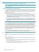
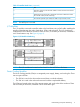
Figure 1 HP M6710 Drive Enclosure (2U24) Figure 2 HP M6720 Drive Enclosure (4U24) Controller Nodes The controller nodes is a storage system component that caches and manages data in a system and provides the hosts with a comprehensive, virtualized view of the system. The controller nodes are located at the rear of the node enclosure. The HP 3PAR StoreServ 7450 Storage system has either two nodes or four nodes. The two-node configuration contains two nodes numbered 0 and 1.
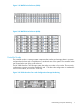
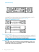
Figure 4 HP 3PAR StoreServ Four-node Configuration Storage Numbering PCIe Slots and Ports This table lists the default port configurations for the HP 3PAR StoreServ 7450 Storage systems.
Table 2 Controller Node Ports (continued) Item Port 3 SAS (DP-2 and DP-1)--used with SAS cables to connect to the drive enclosures and I/O modules 4 Node Interconnect--Used with 4 directional interconnect cables that connect the controller nodes (4-node 7400 only) 5 PCI-e slot for optional 4-port 8 Gb/s FC HBA or 2-port 10 Gb/s CNA NOTE: The MFG port is not used.
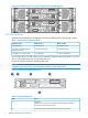
Figure 7 PCM numbering In the HP M6720 Drive Enclosure, the two PCMs are located diagonally from one another. The remaining PCM slots are filled with blank panels (see Figure 8 (page 10)). Figure 8 PCMs in a HP M6720 Drive Enclosure Power Distribution Units In each HP G3 rack, two PDUs are mounted horizontally at the bottom of the rack, numbered 0–1 from bottom to top.
Figure 9 HP 3PAR Service Processor DL 320e Understanding Component Numbering 11
2 Understanding LED Indicator Status Storage system components have LEDs to indicate status of the hardware and whether or not it is functioning properly. These indicators help diagnose basic hardware problems. You can quickly identify hardware problems by examining the LEDs on all components using the tables and illustrations in this chapter. Enclosure LEDs Bezels LEDs The bezels are located at the front of the system on each side of the drive enclosure and include three LEDs.
Disk Drive LEDs These LEDs are located on the front of the disk drives. Figure 11 Disk drive LEDs Table 4 Disk drive LEDs Callout LED Appearance Indicates 1 Activity Green On – Normal operation Flashing – Activity 2 Fault Amber On – Disk failed and is ready to be replaced. Flashing – The locatecage command is issued (which blinks all drive fault LEDs for up to 15 minutes (The I/O module Fault LEDs at the rear of the enclosure also blink). Fault LEDs for failed disk drives do not blink.
Figure 12 PCM LEDs Table 5 (page 14) describes the LED states.
Table 5 PCM LED Descriptions (continued) Icon LED Battery Good Appearance Indicates On Present and charged Flashing Charging or disarmed Green Drive PCM LEDs The following figure shows the location of drive PCM LEDs. Figure 13 Drive PCM LEDs Table 6 (page 15) describes the drive PCM LED states.
Table 6 Drive PCM LED Descriptions (continued) Icon LED DC Output Fail Appearance Indicates On No AC power or fault or out of tolerance Flashing Firmware download Amber I/O Modules LEDs I/O modules are located on the back of the system. I/O modules have two mini-SAS universal ports, which can be connected to HBAs or other ports and each port includes External Port Activity LEDs, labeled 0–3. The I/O module also includes a Power and Fault LED.
Figure 16 I/O Module LEDs Table 7 I/O module LEDs Icon Function Appearance State Meaning Power Green On Power is on Off Power is off On Fault Off Normal operation Flashing Locate command issued Fault Amber External Port Activity LEDs Figure 17 External Port Activity LEDs Function Appearance State Meaning External Port Activity; 4 LEDs for Data Ports 0 through 3 Green On Ready, no activity Off Not ready or no power Flashing Activity Storage System Component LEDs 17
Controller Node and Internal Component LEDs Controller nodes have the following LEDs. NOTE: Issue the locatenode command to flash the hotplug LED blue.
Table 8 Controller Node LEDs Callout LED Appearance Indicates 1 Status Green Node status Good • On – No cluster • Quick Flashing – Boot • Slow Flashing – Cluster 2 Hotplug Blue Node FRU Indicator • On – OK to remove • Off – Not OK to remove • Flashing – locatenode command has been issued 3 Fault Amber Node status Fault • On – Fault • Off – No fault • Flashing – Node in cluster and there is a fault Ethernet LEDs The controller node has two built-in Ethernet ports and each includes two LEDs: F
Figure 21 FC Port LEDs Table 10 FC Port LEDs All ports No light Off Wake up failure (dead device) or power is not applied FC-1 Amber Off Not connected 3 fast blinks Connected at 4GB/sec. 4 fast blinks Connected at 8GB/sec.
Figure 23 Interconnect port LEDs Table 12 Interconnect port LEDs Callout LED Appearance Indicates 1 Status Green On – Link established Off – Link not yet established 2 Fault Amber On – Failed to establish link connection Off – No errors currently on link Flashing – Cluster link cabling error, controller node in wrong slot, or serial number mismatch between controller nodes.
Table 13 Fibre Channel adapter port LEDs (continued) Callout LED Appearance Indicates 4 fast blinks – Connected at 8 GB/sec. 2 Link status Green On – Normal/Connected - link up Flashing – Link down or not connected Converged Network Adapter Port LEDs The CNA in the controller node includes two ports; each has a Link and Activity LED.
Table 15 Front panel LEDs Item LED Appearance Description 1 UID LED/button Blue Active Flashing Blue System is being managed remotely Off Deactivated Green System is on Flashing Green Waiting for power Amber System is on standby, power still on Off Power cord is not attached or power supplied has failed Green System is on and system health is normal Flashing Amber System health is degraded Flashing Red System health is critical Off System power is off Green Linked to network Fl
Table 16 Rear panel LEDs (continued) Item LED Appearance Description 4 Power supply Green Normal Off Off = one or more of the following conditions: • Power is unavailable • Power supply has failed • Power supply is in standby mode • Power supply error 24 Understanding LED Indicator Status
3 Powering Off/On the Storage System The following describes how to power the storage system on and off. Powering Off NOTE: PDUs in any expansion cabinets connected to the storage system may need to be shut off. Use the locatesys command to identify all connected cabinets before shutting down the system. The command blinks all node and drive enclosure LEDs.
Powering On 1. 2. 3. Set the circuit breakers on the PDUs to the ON position. Set the switches on the power strips to the ON position. Power on the drive enclosure PCMs. NOTE: To avoid any cabling errors, all drive enclosures must have at least one or more hard drive(s) installed before powering on the enclosure. 4. 5. 26 Power on the node enclosure PCMs. Verify the status of the LEDs, see “Understanding LED Indicator Status” (page 12).
4 Alerts Alerts are triggered by events that require intervention by the system administrator. This chapter provides a list of alerts identified by message code, the messages, and what action should be taken for each alert. To learn more about alerts, see the HP 3PAR StoreServ Storage Concepts Guide. For information about system alerts, go to HP Guided Troubleshooting at http://www.hp.com/ support/hpgt/3par and select your server platform. To view the alerts, use the showalert command.
6. On the next page, select the message code that matches the one that appeared in the alert. The next page shows the message type based on the message code selected and provides a link to the suggested action. 7. 8. 28 Alerts Follow the link. On the suggested actions page, scroll through the list to find the message state listed in the alert message. The recommended action is listed next to the message state.
5 Troubleshooting The HP 3PAR OS CLI checkhealth command checks and displays the status of storage system hardware and software components. For example, the checkhealth command can check for unresolved system alerts, display issues with hardware components, or display information about virtual volumes that are not optimal. By default the checkhealth command checks most storage system components, but you can also check the status of specific components.
The following information is included when you use the -detail option: Component ----Identifier---- -----------Description------Alert sw_port:1:3:1 Port 1:3:1 Degraded (Target Mode Port Went Offline) Alert sw_port:0:3:1 Port 0:3:1 Degraded (Target Mode Port Went Offline) Alert sw_sysmgr Total available FC raw space has reached threshold of 800G (2G remaining out of 544G total) Alert sw_sysmgr Total FC raw space usage at 307G (above 50% of total 544G) Date -Date is not the same on all nodes LD LD vlun vlun v
Table 18 Component Functions (continued) Component Function PD Displays PDs with states or conditions that are not optimal. Port Displays port connection issues. RC Displays Remote Copy issues. SNMP Displays issues with SNMP. Task Displays failed tasks. VLUN Displays inactive VLUNs and those which have not been reported by the host agent. VV Displays VVs that are not optimal. The following sections provide details about troubleshooting specific components.
Cage Cage Cage Cage Cage cage: cage: cage: cage: cage: "Power supply fan is " "Power supply is " (Degraded, Failed, Not_Present) "Power supply AC state is " "Cage is in 'servicing' mode (Hot-Plug LED may be illuminated)" "Firmware is not current" Cage Example 1 Component -------------Description-------------- Qty Cage Cages missing A loop 1 Cage SFPs with low receiver power 1 Component -Identifier- --------Description--------
0:2 2000001862953303 Green 0:3 2000001862953888 Green 35 0xdc Loop fail 0xdc 31 0xda Loop fail 0xda OK OK cli% showcage -sfp cage4 Cage FCAL SFP -State- --Manufacturer-- MaxSpeed(Gbps) TXDisable TXFault RXLoss DDM 4 0 0 OK FINISAR CORP. 4.1 No No Yes Yes 4 1 1 OK FINISAR CORP. 4.
VendorId,ProductId 3PARdata,DC2 Unique_ID 10320300000AD000 Power Supply Info State Fan State AC Model ps0 Failed OK Failed POI
Cage Example 4 SComponent ---------Description--------- Qty Cage Cages not on current firmware 1 Component -Identifier- ------Description-----Cage cage:3 Firmware is not current Cage Suggested Action 4 Check the drive cage firmware revision using the commands showcage and showcage -d cageX. The showfirwaredb command indicates what the current firmware level should be for the specific drive cage type.
4 cage4 2:2:1 0 3:2:1 0 8 30-37 2.37 2.37 DC4 n/a -----------Cage detail info for cage4 --------Fibre Channel Info PortA0 PortB0 PortA1 PortB1 Link_Speed 2Gbps --- 4Gbps ----------------------------------SFP Info----------------------------------FCAL SFP -State- --Manufacturer-- MaxSpeed(Gbps) TXDisable TXFault RXLoss DDM 0 0 OK SIGMA-LINKS 2.1 No No No Yes 1 1 OK FINISAR CORP. 4.
Format of Possible DAR Exception Messages Dar -- "There are 5 disks that are not self-encrypting" DAR Suggested Action Remove the drives that are not self-encrypting from the system because the non-encrypted drives cannot be admitted into a system that is running with data encryption. Also, if the system is not yet enabled for data encryption, the presence of these disks prevents data encryption from being enabled.
LD Displays Logical Disks (LDs) that are not optimal: • Checks for preserved LDs • Checks that current and created availability are the same • Checks for owner and backup • Checks that preserved data space (pdsld) is the same as total data cache • Checks size and number of logging LDs Format of Possible LD Exception Messages LD LD LD LD ld: ld: ld: ld: "LD "LD "LD "LD is not mapped to a volume" is in write-through mode" has preserved RAID sets and preserv
LD Example 2 Component -------Description-------- Qty LD LDs in write through mode 3 Component -Identifier-- --------Description--------LD ld:Ten.usr.12 LD is in write-through mode LD Suggested Action 2 Examine the identified LDs using CLI commands such as showld, showld –d, showldch, and showpd for any failed or missing disks. Write-through mode (WThru) indicates that host I/O operations must be written through to the disk before the host I/O command is acknowledged.
Examine the identified LDs using CLI commands such as showld, showld –d, showldch, and showpd for any failed or missing disks. In the example below, the LD should have cage-level availability, but it currently has chunklet (disk) level availability (the chunklets are on the same disk). cli% showld -d R1.usr.0 Id Name CPG RAID Own SizeMB RSizeMB RowSz StepKB SetSz Refcnt Avail CAvail 32 R1.usr.0 --1 0/1/3/2 256 512 1 256 2 0 cage ch cli% showldch R1.usr.
License Suggested Action If desired, request a new or updated license from your Sales Engineer. Network Displays Ethernet issues for the Administrative and Remote Copy over IP (RCIP) networks that have been logged in the previous 24-hour sampling window. Reports if the storage system has fewer than two nodes with working admin Ethernet connections. • Check whether the number of collisions is greater than 5% of total packets in previous day’s log.
NOTE: The error counters shown by shownet and shownet -d cannot be cleared except by rebooting a controller node. Because checkhealth is showing network counters from a history log, checkhealth stops reporting the issue if there is no increase in error in the next log entry. shownet -d IP Address: 192.168.56.209 Assigned to nodes: 0123 Connected through node 0 Status: Active Netmask 255.255.255.
Node Node node:1 node:1 Power supply 0 AC state is Failed Power supply 0 DC state is Failed Node Suggested Action 1 Examine the states of the power supplies with commands such as shownode, shownode -s, shownode -ps, and the like. Turn on or replace the failed power supply. NOTE: In the example below, the battery state is considered Degraded because the power supply is Failed; this is normal.
cli% showbattery Node PS Bat Serial -State-- ChrgLvl(%) -ExpDate-- Expired Testing 3 0 0 100A300B OK 100 07/01/2011 No No 3 1 0 12345310 Failed 0 04/07/2011 No No Node Example 3 Component -Identifier- --------------Description---------------Node node:3 Node:3, Power Supply:1, Battery:0 has not been tested within the last 30 days Node Suggested Action 3 The indicated battery has not been tested in the past 30 days.
Format of Possible PD Exception Messages PD PD PD PD PD PD disk: "Degraded States: disk: "Failed States: -- "There is an imbalance of active PD ports" -- "Sparing algorithm is not set" disk: "Disk is experiencing a high level of I/O per second: " -- There is at least one active servicemag operation in progress The following checks are performed when the -svc option is used, or on 7400/7200 hardware: PD File: "Folder not found
Fibre Channel Info PortA0 PortB0 PortA1 PortB1 Link_Speed 2Gbps --- 0Gbps ----------------------------------SFP Info----------------------------------FCAL SFP -State- --Manufacturer-- MaxSpeed(Gbps) TXDisable TXFault RXLoss DDM 0 0 OK SIGMA-LINKS 2.1 No No No Yes 1 1 OK SIGMA-LINKS 2.
48 49 50 51 3:0:0 3:0:1 3:0:2 3:0:3 FC FC FC FC degraded degraded degraded degraded 2:0:4 2:0:4 2:0:4 2:0:4 3:0:4\missing 3:0:4\missing 3:0:4\missing 3:0:4\missing 2/2/2/2/- cli% showcage -d cage3 Id Name LoopA Pos.A LoopB Pos.B Drives Temp RevA RevB Model Side 3 cage3 2:0:4 0 --0 32 29-41 2.37 2.
using statistical monitoring commands/utilities such as statpd, the OS MC (GUI) and System Reporter. The following example reports disks whose total I/O is 150/sec or more. cli% statpd -filt curs,t,iops,150 14:51:49 11/03/09 r/w I/O per second KBytes per sec ... Idle % ID Port Cur Avg Max Cur Avg Max ... Cur Avg 100 3:2:1 t 658 664 666 172563 174007 174618 ...
PD Example 6 Component --Identifier-- -------Description---------PD Disk:32 ST3400755FC PD for cage type DC3 in cage position 2:0:0 is missing from the firmware database PD Suggested Action 6 Check the release notes for mandatory updates and patches to the HP 3PAR OS version that is installed and install as needed to support this PD in this cage.
or contaminated FC connection, such as a cable. An alert should identify the condition, such as the following: Port 0:0:2, SFP Degraded (Receiver Power Low: Check FC Cable) Check SFP statistics using CLI commands such as showport -sfp, showport -sfp -ddm, showcage, etc. cli% showport -sfp N:S:P -State-- -Manufacturer- MaxSpeed(Gbps) TXDisable TXFault RXLoss DDM 0:0:1 OK FINISAR_CORP. 2.1 No No No Yes 0:0:2 Degraded FINISAR_CORP. 2.
Port Example 2 Component -Description- Qty Port Missing SFPs 1 Component -Identifier- -Description-Port port:0:3:1 SFP is missing Port Suggested Action 2 FC node-ports that normally contain SFPs will report an error if the SFP has been removed. The condition can be checked using the showport -sfp command. In this example, the SFP in 0:3:1 has been removed from the adapter: cli% showport N:S:P -State0:0:1 OK 0:0:2 OK 0:3:1 0:3:2 OK -sfp -Manufacturer- MaxSpeed(Gbps) TXDisable FINISAR_CORP. 2.
Port Example 5 Component ------------Description------------ Qty Port Ports with mismatched mode and type 1 Component -Identifier- ------Description------Port port:2:0:3 Mismatched mode and type Port Suggested Action 5 This output indicates that the port's mode, such as an initiator or target, is not correct for the connection type, such as disk, host, ISCSI or RCFC. Useful CLI commands are showport, showport -c, showport -par, showport -rcfc, showcage, etc.
RC Suggested Action Perform remote copy troubleshooting such as checking the physical links between the storage system, and using CLI commands such as showrcopy, showrcopy -d, showport -rcip, showport -rcfc, shownet -d, controlport rcip ping, etc. SNMP Displays issues with SNMP. Attempts the showsnmpmgr command and reports errors if the CLI returns an error.
manually removed with the MC (GUI) or CLI with removealert or setalert ack. To display system-initiated tasks, use showtask -all. cli% showtask -d 6313 Id Type Name Status Phase Step 6313 background_command upgradecage -a -f failed --- --- Detailed status is as follows: 2010-10-22 10:35:36 PDT Created 2010-10-22 10:35:36 PDT Updated 2010-10-22 10:35:36 PDT Errored task.
host1 210100E08B289350 0:5:2 Lun VVName 2 BigVV HostName -Host_WWN/iSCSI_Name- Port Type cs-wintec-test1 10000000C964121D 3:5:1 unknown VV Displays Virtual Volumes (VV) that are not optimal. Checks for VVs and Common Provisioning Groups (CPG) whose state is not normal.
The error can occur for one of the following reasons: • ◦ Network connectivity is lost. ◦ The SP is no longer running. ◦ The SP is not plugged into the network. ◦ The SP IP address has been changed. "Could not communicate with the storage system. Make sure it is running and connected to the network." This message can display if the HP 3PAR OS loses network connectivity, either by becoming unplugged or by going down for some other reason. This message displays either in a dialog box or inline.
For information about contacting HP Support, see “Contacting HP Support about System Setup” (page 61). • “The SP does not have a suitable HP 3PAR OS version installed for the specified storage system. Use SPOCC to install HP 3PAR OS version {0}." This message displays as an inline error on the bottom of the wizard page. The SP needs to have the same Major.Minor.Patch TPD package as the storage system’s HP 3PAR OS.
For information about contacting HP Support, see “Contacting HP Support about System Setup” (page 61). • "The storage system found an error while checking port health. Details are listed below." This error message displays in a dialog box with Retry and Cancel buttons. {0} is the location of the port with the problem. • "The storage system found an error while checking cabling health. Details are listed below." This error message displays in a dialog box with Retry and Cancel buttons.
• “The storage system found an error while checking cage health. There is a problem with a drive cage that has had a firmware upgrade. Cage {0} did not come back after the firmware upgrade. Contact HP support for help.” This error message displays in a dialog box with Retry and Cancel buttons. This error might occur after the drive cages have had a firmware upgrade. {0} will be the name of the cage with the problem. Contact HP Support.
• "Unable to set the storage system network configuration. The specified IPv4 gateway address is not reachable by using the specified storage system IPv4 address." This message displays in a dialog box. The error occurs if the storage system detects that the defined IPv4 gateway address could not be reached. Click Back and specify a valid IPv4 gateway address. If the error persists, contact HP Support. For information about contacting HP Support, see “Contacting HP Support about System Setup” (page 61).
• "Unable to set the storage system time zone. An invalid time zone was specified." This error message displays in a dialog box. This error occurs if the storage system detects that an unfamiliar time zone was selected. Click Back and specify a valid time zone. • "Unable to set the storage system time zone. The storage system saw the time zone as invalid." This error message displays in a dialog box. This error occurs if the storage system detects that an unfamiliar time zone was selected.
• Product model names and numbers • Technical support registration number (if applicable) • Product serial numbers • Error messages • Operating system type and revision level • Detailed questions When you contact HP, specify that you are requesting support for your StoreServ 7450 Storage product.
6 Support and Other Resources Contacting HP For worldwide technical support information, see the HP support website: http://www.hp.
For information about: See: Migrating data from one HP 3PAR storage system to another HP 3PAR-to-3PAR Storage Peer Motion Guide 64 Configuring the Secure Service Custodian server in order to monitor and control HP 3PAR storage systems HP 3PAR Secure Service Custodian Configuration Utility Reference Using the CLI to configure and manage HP 3PAR Remote Copy HP 3PAR Remote Copy Software User’s Guide Updating HP 3PAR operating systems HP 3PAR Upgrade Pre-Planning Guide Identifying storage system compo
For information about: See: Planning for HP 3PAR storage system setup Hardware specifications, installation considerations, power requirements, networking options, and cabling information for HP 3PAR storage systems HP 3PAR 7200, 7400, and 7450 storage systems HP 3PAR StoreServ 7000 Storage Site Planning Manual HP 3PAR StoreServ 7450 Storage Site Planning Manual HP 3PAR 10000 storage systems HP 3PAR StoreServ 10000 Storage Physical Planning Manual HP 3PAR StoreServ 10000 Storage Third-Party Rack Physic
Typographic conventions Table 19 Document conventions Convention Element Bold text • Keys that you press • Text you typed into a GUI element, such as a text box • GUI elements that you click or select, such as menu items, buttons, and so on Monospace text • File and directory names • System output • Code • Commands, their arguments, and argument values • Code variables • Command variables Bold monospace text • Commands you enter into a command line interface • Syste
7 Documentation feedback HP is committed to providing documentation that meets your needs. To help us improve the documentation, send any errors, suggestions, or comments to Documentation Feedback (docsfeedback@hp.com). Include the document title and part number, version number, or the URL when submitting your feedback.