
HP 3PAR StoreServ 7450 Storage Installation Guide

only one network connection is active at a time. If the active network connection fails, the IP
address is automatically moved to the surviving network connection.
• At a minimum, the storage system requires one Fibre Channel (or iSCSI) connection from a
host computer to a controller node. HP recommends separate connections from each host
computer to each of the controller nodes in the storage system, with connections distributed
evenly across all nodes.
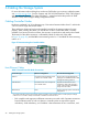
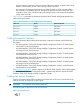
Table 6 (page 39) describes the maximum supported Fibre Channel cable length based on the
cable size and port speed.
Table 6 Cable Limitations for Fibre Channel Host Connectivity
Cable Length LimitSpeedCable Size
100 meters2 Gbps62.5 micron
70 meters4 Gbps62.5 micron
300 meters2 Gbps50 micron
150 meters4 Gbps50 micron
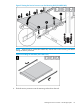
Cabling Expansion Cabinets
For more information about cabling drive enclosures in expansion cabinets, see the following
documents:
• HP 3PAR StoreServ 7000/7450 Storage Cabling Configuration Guide A: 2 Node Systems
with Small 2.5-inch Drive Enclosures
• HP 3PAR StoreServ 7000/7450 Storage Cabling Configuration Guide B: 2 Node Systems
with Large 3.5-inch Drive Enclosures
• HP 3PAR StoreServ 7000/7450 Storage Cabling Configuration Guide C: 2 Node Systems
with Mixed-Size Drive Enclosures
• HP 3PAR StoreServ 7000/7450 Storage Cabling Configuration Guide D: 4 Node Systems
with Small 2.5-inch Drive Enclosures
• HP 3PAR StoreServ 7000/7450 Storage Cabling Configuration Guide E: 4 Node Systems
with Large 3.5-inch Drive Enclosures
• HP 3PAR StoreServ 7000/7450 Storage Cabling Configuration Guide F: 4 Node Systems
with Mixed-Size Drive Enclosures
Visit www.hp.com/go/3par. Scroll to Support, and click HP 3PAR StoreServ 7000/7450 Support
and then Manuals. Then scroll to Setup and install — general and select the specific HP 3PAR
StoreServ 7000/7450 Storage Cabling Configuration Guide.
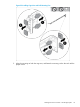
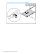
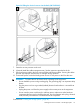
Cabling the Service Processor
Connect a customer-supplied Ethernet cable to the lowest port on the server. Connect the power
cable to PDU, but do not power on at this point.
WARNING! Do not power on the service processor.
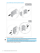
The following icon is typical, but it can vary by server.
Figure 36 Connection Icon
Cabling Expansion Cabinets 39