HP 3PAR StoreServ 7450 Storage Installation Guide nl Abstract This guide is designed to instruct qualified technicians who are authorized to install the HP 3PAR StoreServ 7450 Storage system and associated hardware components.
© Copyright 2014 Hewlett-Packard Development Company, L.P. The information contained herein is subject to change without notice. The only warranties for HP products and services are set forth in the express warranty statements accompanying such products and services. Nothing herein should be construed as constituting an additional warranty. HP shall not be liable for technical or editorial errors or omissions contained herein. Acknowledgments Microsoft® and Windows® are U.S.
Contents 1 General Site Planning.................................................................................6 Pre-Installation Planning.............................................................................................................6 Storage System Rack Shipping Containers...................................................................................7 Acclimatization.........................................................................................................................
Powering On the Storage System..............................................................................................43 Verifying LED Status................................................................................................................44 Node Interconnect Ports......................................................................................................47 Drive Enclosure LEDs......................................................................................................
Inserting Hard Drives..........................................................................................................96 Checking Status.................................................................................................................96 Checking Progress.............................................................................................................97 Completing the Upgrade....................................................................................................
1 General Site Planning Successful installation of the HP 3PAR StoreServ 7450 Storage system requires careful planning and supervision in collaboration with authorized HP representatives. Proper planning will help provide for a more efficient installation and greater reliability, availability, and serviceability. The chapter includes general recommendations for physical planning and site preparation for the storage system installation.
• Verify the electrical service wiring has been installed at the predetermined location before installing the storage system. Refer to the respective product specifications for detailed requirements. • Verify any additional support equipment is properly installed and operational. Prior to installation, review the packaging to make sure the goods have not been tampered with. When unpacking the equipment, verify the delivered shipment of all the equipment is correct.
NOTE: See HP 3PAR StoreServ 7450 Storage Site Planning Manual for more information on placing the storage systems and reserving room for service access. Acclimatization Storage systems are shipped or stored at extreme temperatures and may require time to adjust to operating temperatures before startup. The maximum acceptable rate of temperature change for a non-operating system is 68° F/hour (20° C/hour).
2 Getting Started Before you begin, read the following guidelines to help you complete the installation successfully. If you need assistance with the installation, contact HP Support or visit http://www.hp.com/support. Tools The following tools are not required but can be useful, especially when unpacking or installing the storage system. CAUTION: Always wear an electrostatic discharge (ESD) wrist-grounding strap when installing a storage system hardware part.
• Cover workstations with approved static-dissipating material. Use a wrist strap connected to the work surface, and properly grounded (earthed) tools and equipment. • Keep the work area free of nonconductive materials, such as plastic assembly aids and foam packing. • Ensure that you are always properly grounded (earthed) when touching a static-sensitive component or assembly. • Avoid touching pins, leads, and circuitry. • Always place drives with the printed circuit board assembly-side down.
Redeeming and Registering HP 3PAR Licenses HP 3PAR StoreServ 7450 products include 3PAR licensing, which enables all system functionality. Failure to register the license key may limit access and restrict system upgrades. The Summary Entitlement Certificate is enclosed in a blue envelope in the accessories kit shipped with the system. The certificate must be redeemed through the HP Licensing for Software portal before you begin installing the hardware and software components.
3 Identifying Storage System Components NOTE: The illustrations in this chapter are examples only and may not accurately represent your storage system configuration. Understanding Component Numbering Due to the large number of potential configurations, component placement and internal cabling is standardized to simplify installation and maintenance.
Figure 2 HP M6720 Drive Enclosure (4U24) In the HP 3PAR Management Console or CLI, the enclosures are displayed as follows: DCS2 for the 2U24 (M6710), DCS1 for the 4U24 enclosure (M6720), and DCN1 for the 7450 controller node enclosure. Controller Nodes The controller node is a storage system component that caches and manages data in a system and provides hosts with a coherent, virtualized view of the system. Controller nodes are located in the rear of the node enclosure.
Controller Node PCIe Slots and Ports Table 1 (page 14) describes default configurations for the HP 3PAR StoreServ 7450 Storage system: Table 1 Storage System Expansion Cards Expansion cards Nodes 0 and 1 Nodes 2 and 3 2 FC HBAs only 1 FC HBA each No expansion card 2 10 Gb/s converged network adapter (CNA) only 1 10 Gb/s CNA each No expansion card 2 FC HBAs + 2 10 Gb/s CNAs 1 FC HBA each 1 10 Gb/s CNA each NOTE: If you are upgrading from a two-node to a four-node configuration, you can have CNAs
I/O Modules The I/O modules connect the controller nodes to the hard drives using a SAS cable, enabling the transfer of data between the nodes, hard drives, PCMs, and enclosures. The I/O modules are located at the rear of the drive enclosure. There are two I/O modules per enclosure, numbered 0 and 1 from bottom to top (see Figure 6 (page 15) and Figure 7 (page 15)).
Figure 9 PCM Numbering for HP 3PAR 7450 (4U) Controller Node Enclosure NOTE: In the HP M6720 Drive Enclosure, the two PCMs are located diagonally from one another. The remaining PCM slots are filled with blank panels (see Figure 10 (page 16) and Figure 11 (page 16)). Figure 10 PCM Numbering for HP M6710 Figure 11 PCM Numbering for HP M6720 Service Processor The HP 3PAR StoreServ 7450 Storage system can include an HP 3PAR Service Processor (SP) or a Virtual Service Processor (VSP).
Power Distribution Units In each HP G3 rack, two PDUs are mounted horizontally at the bottom of the rack, numbered 0–1 from bottom to top. The default configuration for the HP Intelligent Series Racks is two PDUs mounted vertically at the bottom of the rack so to provide a front-mounting unit space. Make sure there is enough clearance for service. For example, the PDUs mounted vertically at the back of a rack must have enough clearance to remove node and drive chassis power supples.
4 Setting Up a Factory-Integrated Storage System This chapter describes the procedures for setting up a storage system that is delivered in a factory-integrated HP cabinet with all of the components installed. Before you set up a storage system, ensure all requirements documented in the HP 3PAR StoreServ 7450 Storage Site Planning Manual have been met. WARNING! Do not perform these procedures if you are installing storage system components in an existing or partially populated rack.
Verify the Cabling The cabling for a factory-integrated storage system is complete. You must plug in the power cords and install the host and Ethernet cables. NOTE: In a 7450 four controller nodes system, two cable management brackets have Velcro straps to hold the cables. You can remove and discard these brackets, but HP recommends saving them for future use. To remove the cable management brackets, loosen the Torx screws and unlatch the Velcro straps to free the cabling.
4. Attach the brackets to the side rails (see Figure 14 (page 20)). Be careful not to damage the data cables. Figure 14 Attaching the Brackets to the Side Rails 5. Tighten the captive screws (see Figure 15 (page 20)). NOTE: Make sure the brackets are aligned and leveled with the link connectors before tightening the captive screws. HP recommends tightening the screws to 19 in-lbs.
Removing the Brackets Remove the cable restraint shipping brackets only when the cabinet is in its final location. 1. Remove the data cables from the hook and loop straps. 2. Loosen the captive screws (see Figure 16 (page 21). Figure 16 Loosening the Captive Screws 3. Remove the brackets. Be careful not to damage the attached data cables.
5 Installing Storage System Components into a Rack This chapter describes the procedures for installing storage system components in an existing rack. Before you set up a storage system, ensure that all requirements documented in the HP 3PAR StoreServ 7450 Storage Site Planning Manual have been met.
Mounting a 2U rail shelf onto the rack 1. Determine the location of the directional-specific rail matches with the side of a rack post. The following text is imprinted on both ends of the rails: FRONT-R and FRONT-L. 2. 3. 4. Align one end of the rail channel with the holes of the rack post, and then push to seat the locating pins in the rack. Expand the rail to connect to the other end of rack post.
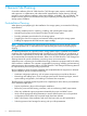
5. Install the middle support bracket before transporting: a. Align the middle support bracket holes with the top holes of the rail(s). The orientation of the middle support bracket is neutral. b. Insert and tighten screws. Figure 18 Installing the Middle Support Bracket 6. 7. Repeat steps 1 through 5 for the other rail. Snap one cage nut into the rack hole two positions above the rail on both sides. Figure 19 Installing the Cage Nut 8.
Installing PCIe Adapters in the Controller Nodes PCIe adapters connect the controller nodes to host computers and hard drives. Installing or upgrading PCle adapters involves adding additional supported types of adapters or replacing existing adapters. WARNING! FC HBA and iSCSI CNA upgrades on the HP 3PAR StoreServ 7450 four controller node system must be serviced by authorized service personnel and cannot be done by a customer. Contact your local service provider for assistance.
1. Determine that the enclosure is oriented correctly by looking at the rear of the enclosure. Verify the node numbering by reviewing the controller node label on both edges of the enclosure slot. Figure 20 Verify Controller Node Numbering 2. 3. 4. 5. At the front of the enclosure, remove the yellow bezels on each side of the enclosure to expose the mounting holes. Slide the enclosure onto the rail shelves. Use both hands to handle the enclosure.
8. 9. Remove the blank filler panels before Installing the hard drives into the slots. To ensure proper thermal control, install blank filler panels into any empty slots. Guidelines for Installing Hard Drives in Drive Enclosures This section provides information about the requirements and installation order for hard drives in SFF and LFF drive enclosures. Only 2.5-inch drives can be installed in HP 3PAR 7200/7400 controller node enclosures and HP M6710 (2U) drive enclosures. The 3.
Figure 23 M6720 Drive Enclosure (4U24) Hard Drive Placement Order Guidelines for Allocating and Loading Order (Mixed SFF and LFF hard drives) In a storage system with mixed HP M6710 and M6720 drive enclosures, there is a minimum of three pairs of drives for each drive enclosure. Additional upgrades can include all SFF, LFF, or a mixture of SFF and LFF drives, but they must be in pairs of the same drive type. Follow the loading order as in the sections above for SFF and LFF drives.
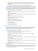
Figure 24 Installing a 2.5 inch Hard Drive Installing a 3.5 inch Hard Drive (LFF) 1. 2. 3. Press the handle latch to open the handle. Position the hard drive so the handle opens from the left, and slide it into the enclosure. Push firmly until the handle fully engages and clicks. Figure 25 Installing a 3.
Installing the Service Processor in the Storage System The HP 3PAR Service Processor consists of the following: • A standard HP Server • A 1U Rail Kit for that specific server NOTE: The SP ID is the HP 7-digit serial number of the array located on the top front of the server and in a pull-out placard in the front of the server. The serial number is preceded by SP000. For example, if the 3PAR serial number is 1614983, enter SP0001614983.
Figure 26 Rail Kit Components (PN 683811-001) Figure 27 Rail Kit Components (PN 714501-001) In addition to the supplied items, you may also need the following: • Screws fitting a threaded-hole rack • Screwdriver • Optional cable management arm (see Figure 28 (page 32)) Installing the Service Processor in the Storage System 31
Figure 28 Cable Management Arm WARNING! To avoid risk of injury or damage to the equipment, do not stack anything on top of rail-mounted equipment or use it as a work surface when it is extended from the rack. CAUTION: Always plan the rack layout before installing the equipment. See HP 3PAR StoreServ 7000/7450 Cabling Configuration Guide for the best practices for node and drive enclosure positioning in specific configurations. To install the rail kit and service processor: 1.
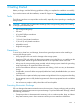
Figure 29 Installing Cage Nuts and Rail Mounting Pins 3. Align the mounting rail with the cage nuts, and fasten the mounting rails to the rack with the proper screws.
Figure 30 Mounting and Fastening the Mounting Rails 4. Repeat steps 1 through 3 for the other mounting rail. WARNING! To prevent the risk of injury or equipment damage, inspect the rack to ensure that it is adequately stabilized before installing the service processor. 5. 34 Install the side rails on each side of the service processor by aligning each side rail to the component, and then snapping it into place.
Figure 31 Setting the Service Processor onto the Mounting Rails (PN 683811-001) NOTE: Align the rail pin guides (PN 683811-001) with the slots on the mounting rails before setting the service processor. Figure 32 Installing the Side Rails (PN 714501–001) 6. Slide the service processor onto the mounting rails and into the rack.
Figure 33 Sliding the Service Processor into the Rack (PN 683811-001) 36 Installing Storage System Components into a Rack
Figure 34 Sliding the Service Processor into the Rack (PN 714501-001) 7. 8. 9. Fasten the service processor to the rack. (Optional) Install the cable management arm. See the instructions provided in the kit. Use the straps provided in the kit to secure all fiber and Ethernet cables. Securing the cables prevents any improper disconnection or damages during operation. 10. Connect the power cord to the facility power source. Do not power on the SP at this time.
6 Cabling the Storage System For more information about cabling drive enclosures (SAS) before you continue to cable the system, visit www.hp.com/go/3par. Scroll to Support, and click HP 3PAR StoreServ 7000/7450 Support and then Manuals. Then scroll to Setup and install — general and select the specific HP 3PAR StoreServ 7000/7450 Storage Cabling Configuration Guide. Cabling Controller Nodes Nodes are numbered 0 to 3 from bottom to top.
only one network connection is active at a time. If the active network connection fails, the IP address is automatically moved to the surviving network connection. • At a minimum, the storage system requires one Fibre Channel (or iSCSI) connection from a host computer to a controller node. HP recommends separate connections from each host computer to each of the controller nodes in the storage system, with connections distributed evenly across all nodes.
Cabling Power to the Storage System WARNING! Before you begin cabling the power cords, verify your power connections are set up correctly. See “Verifying Power Connections” (page 42). When routing PCM power cords, ensure power redundancy is maintained by connecting each PCM within a shelf to a different PDU. When observed from the rear, the left side cabling (ID #0) is black, and the right side cabling (ID #1) is gray.
3. Ensure the PDUs are in a fully lowered position before accessing. Figure 37 Disengaging the PDU Pivot Brackets Cabling the Power Strips Power strips can be located on the side of the rack to supply power to the PCMs. Power strips are connected to PDUs. Do not exceed the capabilities of power strips and PDUs. Continue on to “Verifying Setup and Powering On the Storage System” (page 42).
7 Verifying Setup and Powering On the Storage System This section describes the verification of procedures for setting up and powering on all components in the storage system. NOTE: To avoid any cabling errors, all drive enclosures must have at least one or more hard drives installed before powering on the enclosure. Verifying Setup To complete the installation, you must verify the power connection and final positioning and then power on the storage system.
Acclimating the Storage System Before powering on the storage system, the system may require up to 24 hours to acclimatize to the new operating environment when outside-to-inside conditions vary significantly. If the system or its components may have experienced environmental changes during the transit, allow enough time for the system to acclimatize before proceeding with the power-on sequence.
Verifying LED Status 1. At the front of the storage system, verify the bezel and hard drive LEDs are illuminating green. NOTE: If any module fault or hard drive LEDs are not green, do not proceed until the problem is resolved.
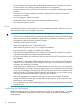
Figure 39 Hard Drive LEDs Table 8 Identifying Hard Drive LEDs Item Description 1 Amber LED indicates a fault. 2 Green LED indicates the system is ready.
2. At the rear of the storage system, verify that the controller node, I/O modules, and PCM LEDs are lit green. The controller node LEDs should be blinking green once per second. The green LED of each node will blink together when the storage cluster is properly formed. Figure 40 Node Enclosure PCM LEDs Figure 41 Controller Node LEDs NOTE: The batteries are fully charged during shipment. The batteries may loose some charge and show a degraded status immediately when power is applied.
Node Interconnect Ports The node interconnect ports are used only with the 7450 four controller nodes system. Figure 42 7450 Four Controller Node LEDs Table 9 Node Interconnect Ports LEDs Item Description 1 Green LED 2 Amber LED Solid (not flashing) green LEDs indicate normal operation.
Drive Enclosure LEDs Figure 43 Drive Enclosure PCM LEDs CAUTION: Do not proceed without first correcting all fault indications (except for PCM batteries). The cluster is not formed until the storage system software installation has been performed.
Identifying Service Processor LEDs The HP 3PAR SP (Proliant DL320e) LEDs are located at the front and rear of the SP.
Figure 45 Rear Panel LEDs Table 11 Rear panel LEDs Item LED Appearance Description 1 NIC link Green Link Off No link Green or Flashing Green Activity Off No activity Blue Active Flashing Blue System is being managed remotely Off Deactivated Green Normal 2 3 4 NIC status UID LED/button Power supply NOTE: May not be applicable to Off your system (for hot-plug HP CS power supplies ONLY) Off = one or more of the following conditions: • Power is unavailable • Power supply has failed
8 Initializing the Service Processor The SP supports all actions required for maintenance of the storage system. The service processor provides real-time, automated monitoring and remote access to HP 3PAR Support in order to diagnose and resolve potential problems. An HP 3PAR StoreServ system can include either a virtual or physical SP. Use the following table as guidance for setting up a specific type of service processor.
Deploying the VSP OVF File NOTE: The virtual service processor supports VMware ESXi versions 4.1 and later. For more specific VMware environment support, see the VMware compatibility matrix on the VMware website. The following set of instructions may vary depending on the version of VMware ESXi you are using. 1. 2. 3. 4. 5. 6. 7. Insert the HP 3PAR Virtual Service Processor software DVD. In the VMware vSphere Client window, select File > Deploy OVF template.
3. Continue on to “Setting Up the Service Processor and Storage System” (page 57) to set up the VSP with SmartStart over the public network. If you are not using SmartStart, see “Installing HP 3PAR Storage Software When HP 3PAR SmartStart is Unavailable” (page 99) to manually launch the setup wizards. Option B: Non-DHCP Environment To set the IP address of the VSP: 1. In the VMware vSphere Client window, select the Console tab, click anywhere on the screen, and press Enter. 2. Log on as setupusr.
Connecting to a Physical Service Processor Use the following instructions to connect to a physical service processor installed in the rack. Do not continue with the section if you are using a VSP. Configuring the Physical Service Processor IP Address The following example uses Microsoft Windows 7™ to configure the SP IP address and the procedures may vary depending on the type of OS being used. 1.
Figure 47 Assign IP Address While you are entering an IP address, the IP Address field indicates an error. After you have entered a valid IP address, the Subnet Mask and Gateway fields are automatically populated. Figure 48 Subnet Mask and Gateway Fields Populated You can customize settings for the Subnet Mask and Gateway if required. 7. Select Next, review the Summary screen, and then select Next when you are ready. The settings are applied.
11. Continue on to“Setting Up the Service Processor and Storage System” (page 57) and set up the SP with SmartStart over the public network. If you are not using SmartStart, see “Installing HP 3PAR Storage Software When HP 3PAR SmartStart is Unavailable” (page 99).
9 Setting Up the Service Processor and Storage System Before you begin setting up the storage system, review and complete the following tasks: • Complete the storage system installation checklists below. • Verify Microsoft Windows 2008 R2 or 2012 is currently running. Windows 2008 R2 or 2012 is required to perform host configurations. If the system does not meet the requirements, you can proceed with the software installation without using HP 3PAR SmartStart.
Table 12 SP and Storage System Software Installation Checklist (continued) Date and time: Enter manually Use NTP server information Time Zone New password to assign setupusr (for use with the system setup wizards) NOTE: All passwords for the setupusr username must be between 7 and 32 characters in length and can consist of alphanumeric characters and the following special characters: period (.), plus (+), dash (-), equal (=), and forward slash (/).
SmartStart Prerequisites • Microsoft Windows 2008 R2 Server x64 Edition or 2012 is currently running in the system • 1.0 gigahertz or higher processor • 1 GB of installed RAM (2 GB recommended) • CD-ROM or DVD-ROM drive • 1280 x 1024 or better screen resolution SmartStart Online Help is supported in the following browser versions: • Microsoft Internet Explorer 8, 9 and 10 • Mozilla Firefox 14 through 21 After completing the checklist, continue on to “Launching HP 3PAR SmartStart” (page 59).
• Time and Region • Change Passwords • Summary • Applying Settings • Finish To launch the wizards in SmartStart: 1. Verify the service processor is powered on. 2. Click the Initialize Service Processor link in SmartStart wizard step 2, Initialize Service Processor. 3. Enter the SP IP address and click OK. NOTE: When configuring in a DHCP network environment, enter the VSP temporary IP address.
Welcome Page The Welcome page shows the information that is required to complete the wizard and set up the SP. Follow the instructions on each screen, and then click Next. The setup takes about 15 minutes.
Generate Service Processor ID This page simplifies the process of creating the SP ID. 1. Enter the StoreServ serial number. Figure 51 Serial Number Label Locations NOTE: The StoreServ 7-digit serial number is located on the back of your HP 3PAR storage system next to the power switch for the node enclosure PCM, and it begins with 16 (for example, 1624635). 2. 62 Click Generate SP ID.
Figure 52 Generating SP ID Page NOTE: During the SP Setup process, the StoreServ must be powered on, connected to the same network subnet as the SP, and non-initialized to allow the SP to verify the StoreServ serial number. 3. After the SP ID is generated, click Next. Configure SP Networking To complete this section, use the completed installation checklist from HP 3PAR StoreServ 7450 Site Planning Manual as reference.
2. If applicable, check the Enable DNS Support box and provide the values for the following fields: • Domain Name • DNS Server(s) To adjust the network speed, expand the Advanced option to change the settings. If you are setting up a VSP in DHCP network environment, enter the permanent IPv4 address you want to assign to it. CAUTION: Be sure to enter the permanent SP IP address.
Remote Support sends diagnostic information, such as system health statistics, configuration data, performance data, and system events, to HP 3PAR Central. These diagnostics are required for HP to perform fault detection and analysis on your HP 3PAR StoreServ Storage system that help maximize your storage availability. All remote communications are encrypted and transferred securely to HP 3PAR Central, and no customer application data is ever transferred.
3. To mask identifying information in all Service Processor log files, select the Make contents of Service Processor log files anonymous box in the Advanced pane. When you make the log files anonymous, the Remote Support process replaces object names in log files (such as TopSecretVirtualVolume) with meaningless sequential labels (such as VVnnn). 4. Click Next to continue the SP configuration. This wizard enables Remote Support upon completion.
3. • Technical contact last name • Phone number • Fax number • Email address for service alert notification Click Next. Figure 55 System Support Information Page Time and Region On the Time and Region page, the Manual option is selected and automatically populated with the current host Web browser time by default. If you select Automatic, complete the NTP Server(s) field and click Test to get the specified NTP time.
Figure 56 Time and Region Page Change Passwords NOTE: All passwords for the setupusr and 3parcust usernames must be between 7 and 32 characters in length and consist of alphanumeric characters and the following special characters: period (.), plus (+), dash (-), equal (=), and forward slash (/). • Enter a new, secure password for the username setupusr. You will use this username and password to access the Storage System Setup wizard and set up your storage system.
Figure 57 Change Passwords Page Launching the HP 3PAR Service Processor Setup Wizard 69
Summary The Summary page shows all the selected options and this page cannot be modified. To modify the selected options, click Prev. To proceed, click Next. Figure 58 Summary Page Applying Settings The Apply Settings page shows the setup process and operation status. The arrows indicate the operation is in progress, and the check marks indicate the operation is complete. Click OK to finish setting up the Service Processor.
Figure 59 Apply Settings Finish The Finish page describes the status of the SP setup. Click Finish.
The HP 3PAR Service Processor is setup is now complete. Continue on to “Launching the HP 3PAR Storage System Setup Wizard” (page 72). Launching the HP 3PAR Storage System Setup Wizard The setup wizard proceeds through the following steps: • Welcome • Enter Storage System • Verify Storage System • Configure Networking • Configure Time • Change Password • Verify Configuration • Progress • Results To launch the storage system setup wizard in SmartStart: 1.
Welcome The Welcome page shows the information that is required to complete the wizard and set up the SP. Follow the instructions on each page, and then click Next.
Figure 63 Enter Serial Number Page NOTE: The following illustration points to the location of the serial number which is situated on the side of the right rear node enclosure PCM and adjacent to the power switch. The serial number begins with 16 (for example, serial number: 1624635).
Verify Storage System On the Verify Storage System page, verify all the system information is correct, and then click Next. Figure 65 Verify Storage System Page Configure Networking On the Configure Networking page, complete the required fields and click Next.
Figure 66 Configure Networking Page Configuring Time On the Configure Time page, the Copy time options from the Service Processor option is selected by default and is automatically populated with the time and date entered in the SP wizard. Select the Enter data and time manually option if you want to manually enter the date and time. If you select Automatic, complete the NTP Server field and click Test to get the specified NTP time. In the Time Zone section, select the appropriate region. Click Next.
Change Password This login profile is used to add this storage system to the Service Processor and for initial administrative access to the storage system. When updating of password is complete, click Next. NOTE: Passwords for the 3paradm username can include all printable characters and be between 6-8 characters in length.
Verify Configuration The Verify Configuration page shows all the selected options and this page cannot be modified. To modify the selected options, click Prev. To proceed, click Next. Figure 69 Verify Configuration Page Progress The Progress page shows the setup process and operation status. The arrows indicate the operation is in progress, and the check marks indicate the operation is complete.
Figure 70 Progress Page Results The Results page confirms the storage system is ready to use. Click Finish.
Post-Installation System Tasks The storage system setup is now complete. Perform the recommended tasks before using the system: • Validating Remote Support For more information, see “Validating Remote Support” (page 100). • Setting up notifications, performing system Health Check and InSplore with SPOCC For more information, see HP 3PAR Service Processor Onsite Customer Care User's Guide.
10 Support and Other Resources Contacting HP For worldwide technical support information, see the HP support website: http://www.hp.
For information about: See: Migrating data from one HP 3PAR storage system to another HP 3PAR-to-3PAR Storage Peer Motion Guide 82 Configuring the Secure Service Custodian server in order to monitor and control HP 3PAR storage systems HP 3PAR Secure Service Custodian Configuration Utility Reference Using the CLI to configure and manage HP 3PAR Remote Copy HP 3PAR Remote Copy Software User’s Guide Updating HP 3PAR operating systems HP 3PAR Upgrade Pre-Planning Guide Identifying storage system compo
For information about: See: Planning for HP 3PAR storage system setup Hardware specifications, installation considerations, power requirements, networking options, and cabling information for HP 3PAR storage systems HP 3PAR 7200, 7400, and 7450 storage systems HP 3PAR StoreServ 7000 Storage Site Planning Manual HP 3PAR StoreServ 7450 Storage Site Planning Manual HP 3PAR 10000 storage systems HP 3PAR StoreServ 10000 Storage Physical Planning Manual HP 3PAR StoreServ 10000 Storage Third-Party Rack Physic
Typographic conventions Table 14 Document conventions Convention Element Bold text • Keys that you press • Text you typed into a GUI element, such as a text box • GUI elements that you click or select, such as menu items, buttons, and so on Monospace text • File and directory names • System output • Code • Commands, their arguments, and argument values • Code variables • Command variables Bold monospace text • Commands you enter into a command line interface • Syste
11 Documentation feedback HP is committed to providing documentation that meets your needs. To help us improve the documentation, send any errors, suggestions, or comments to Documentation Feedback (docsfeedback@hp.com). Include the document title and part number, version number, or the URL when submitting your feedback.
A HP 3PAR StoreServ 7450 (Controller and Storage) and M6700 Series (Storage) Contents List The following components may vary, depending on system configuration: • Appearance of components • Quantity of components • Whether or not the component is included with the system HP 3PAR StoreServ 7450 and M6700 Components Figure 72 2U Enclosure Figure 73 4U Enclosure 86 HP 3PAR StoreServ 7450 (Controller and Storage) and M6700 Series (Storage) Contents List
Figure 74 7450 Series Controller Figure 75 M6700 Series I/O Module Figure 76 7450 Series PCM HP 3PAR StoreServ 7450 and M6700 Components 87
Figure 77 M6700 Series PCM Figure 78 SFF Drive Assembly Blank Figure 79 SFF Drive Assembly 88 HP 3PAR StoreServ 7450 (Controller and Storage) and M6700 Series (Storage) Contents List
Figure 80 LFF Drive Assembly Blank Figure 81 LFF Drive Assembly Figure 82 7450 Series Battery (Installed in 7450 Series PCM) HP 3PAR StoreServ 7450 and M6700 Components 89
Accessory Kits The following accessory kits can be included with your system: • Power cords • SAS cables • Cable bundle ties • Hook and loop straps • Product documentation • Various enclosure labels • RJ45 to serial crossover cable • RJ45 to serial cable • CAT5 cable • Ethernet crossover cable • Enclosure rack mounting fasteners • Software kits • Entitlement certificate • Node CSR and HBA CSU limitations • 1U filler panels • Link cables • Shipping bracket kit Service Proces
Figure 84 Right and Left 2U Rail Subassembly (Right Subassembly Shown) Figure 85 Right and Left 4U Rail Subassembly (Right Subassembly Shown) Figure 86 M5 Shoulder Screw for Rack Mount Figure 87 M5 Screw for Middle Support Bracket Rail Kits 91
Figure 88 Middle Support Bracket Figure 89 M5 Cage Nut 92 HP 3PAR StoreServ 7450 (Controller and Storage) and M6700 Series (Storage) Contents List
B Enhancing Security with Data Encryption HP 3PAR Data Encryption security feature allows you to encrypt all specifically formatted hard drives on the storage system with an authentication key and the use of Self Encrypting Drives (SEDs). When a Data Encryption license is registered, you must manually enable the encryption feature on the system. When the encryption feature is enabled successfully, all the drives in the system become automatically set in an encrypted state.
C Adding Hard Drives and Expansion Drive Enclosures HP 3PAR StoreServ 7450 products include 3PAR licensing that enables all functionality associated with the system. A failure to register the license key may limit access and restrict upgrading of your system. Before you proceed with upgrading, verify all applicable licenses associated with the system are registered. For assistance with registering HP software licenses, visithttp://hp.com/support.
NOTE: NOTE: SSDs have a limited number of writes that can occur before reaching the SSD's write endurance limit. This limit is generally high enough so wear out will not occur during the expected service life of an HP 3PAR StoreServ under the great majority of configurations, IO patterns, and workloads. HP 3PAR StoreServ tracks all writes to SSDs and can report the percent of the total write endurance limit that has been used.
Adding Hard Drives There are five processes for adding hard drives: • Checking initial status • Inserting hard drives • Checking status • Checking progress • Completing the upgrade Checking Initial Status Under Systems, select Physical Disks, and in the right pane, select the Physical Disks tab. Figure 92 Physical Disks Tab Inserting Hard Drives In this example, two hard drives are added to each of the three enclosures.
Figure 93 New State of Inserted Hard Drive Within 6 minutes (depending on the system load and the size of the upgrade), the State of the new hard drives changes to Normal, and the system starts to initialize the chunklets to ready for use. Output indicates that each of the six added hard drives still have normal and spare chunklets to be initialized. NOTE: The system can be used normally, but newly added capacity must be initialized before it can be allocated.
Completing the Upgrade In the Systems pane, select myStorageSystem - Physical Disks, and then select the Physical Disks tab. On the Physical Disks tab, in the drop-down list, select Chunklet Usage. Figure 95 Upgrade Completion Display Chunklet initialization can take several hours to complete and the output of the available capacity is displayed. NOTE: The system can be used normally, but newly added capacity must be initialized before it can be allocated.
D Installing HP 3PAR Storage Software When HP 3PAR SmartStart is Unavailable Use the following instructions to manually launch the setup wizards to configure the SP and StoreServ from a browser if you are not using HP 3PAR SmartStart or SmartStart is unavailable. Review the prerequisites and information about storage and system components before proceeding.
E Validating Remote Support After making any networking changes or if the Service Processor Setup Wizard is unable to verify remote support connectivity, use the SPMaint module in SPOCC to test the communication with remote support. NOTE: For a current list of supported browsers for SPOCC, see the Single Point of Connectivity Knowledge for HP Storage Products (SPOCK), located at http://www.hp.com/storage/spock. 1. 2. 3. Open a supported type of web browser.
Figure 98 SPOCC Communication Results 7. Verify the Service Processor is transferring files successfully by doing the following steps: a. Click Home to return to the SPOCC home page. The Transfer Status entry indicates the overall status of SP file transfer. b. c. To access the SP File Transfer Monitor, click Transfer Status. Verify the SP file transfer is successful: • The Last transfer status entry should include information about the last SP transfer, including the date and time and a status of Ok.
F Troubleshooting Troubleshooting Duplicate IP Address Issues If the wizard cannot configure the permanent IP address you entered because it is already in use: 1. Click Stop to stop the Apply Settings process and return to the Service Processor Setup wizard. 2. Click the Prev button until you reach Step 2: SP Networking. 3. Determine an available IPv4 address to use for the Service Processor and enter that IP address in the IP Address text box. 4.