
HP 3PAR InForm OS 3.1.1 Concepts Guide

NOTE: For information about port location and numbering, see “Port Location Formats” (page 29).
NOTE: For information about how to view the control cache DIMM and data cache DIMM
configurations for each controller node, see the HP 3PAR HP 3PAR InForm OS CLI Administrator's
Manual and InForm OS Management Console Online Help. For information about memory
expansion, contact your HP representative.
NOTE: For a complete list of supported third-party hardware and software, go to the Single Point
of Connectivity Knowledge (SPOCK) website http://spock.corp.hp.com/index.aspx.
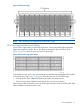
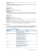
P10000 Controller Node Numbering
The P10000 system may contain two, four, six or eight controller nodes per system configuration.
The controller node chassis is located at the rear of the storage cabinet.
From the rear of the storage cabinet, component numbering starts with zero (0) at the bottom-left
corner and advances right and upward. For example, the node in the lower left position is identified
as node 0 and the adjacent node (right) is identified as node 1. When two node chassis are
present, the orientation of the lower and upper nodes becomes inverted. The node located in upper
right corner of a P10000 with 8 nodes is identified as node 7.
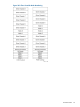
The following figure shows the numbering and positioning of the controller nodes in a P10000
chassis:
Figure 18 P10000 Controller Node Numbering
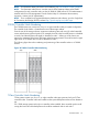
T-Class Controller Node Numbering
T-Class systems contain two, four, six, or eight controller nodes per system and only use T-Class
controller nodes. Controller nodes are loaded into the system backplane enclosure from bottom to
top.
For a T800 storage system with only two controller nodes installed, those controller nodes would
occupy the lowest 4U of the backplane and would be numbered node 6 and node 7.
Controller Nodes 63