
HP 3PAR InForm OS 3.1.1 Concepts Guide
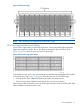
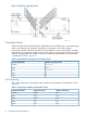
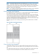
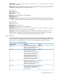
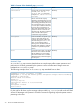

Figure 15 DC4 Drive Cage
NOTE: Daisy chaining is not supported for the DC4 drive cages.
DC3 Drive Cage and Ports and Cabling
The DC3 drive cage contains 16 drive bays at the front, each accommodating the appropriate
plug-in drive magazine module. The 16 drive bays are arranged in four rows of four drives.
Figure 16 (page 61) shows the front view of a DC3 drive cage.
Figure 16 DC3 Drive Cage (Front View)
In the DC3 drive cage, two FC-ALs, each providing four small form-factor pluggable (SFP) modules
to service the drive cage. Figure 17 (page 62) shows the rear view of a DC3 drive cage.
• FC-AL B has four ports, labeled Port B0 through Port B3, from bottom to top.
• FC-AL A has four ports, labeled Port A0 through Port A3, from top to bottom.
Fibre Channel cables connect the ports in the drive cage to the ports on the controller nodes. Each
cable is labeled to indicate the ports it uses.
Drive Cage Models 61