HP 3PAR InForm® OS 3.1.1 Concepts Guide Abstract This guide is for all levels of system and storage administrators. Anyone who plans storage policies, configures storage resources, or monitors the storage usage of HP 3PAR Storage Systems should read this guide.
© Copyright 2007–2012 Hewlett-Packard Development Company, L.P. The information contained herein is subject to change without notice. The only warranties for HP products and services are set forth in the express warranty statements accompanying such products and services. Nothing herein should be construed as constituting an additional warranty. HP shall not be liable for technical or editorial errors or omissions contained herein. Acknowledgments Microsoft®, Windows®, Windows® XP, and Windows NT® are U.S.
Redistribution and use in source and binary forms, with or without modification, are permitted provided that the following conditions are met: 1. Redistributions of source code must retain the above copyright notice, this list of conditions and the following disclaimer. 2. Redistributions in binary form must reproduce the above copyright notice, this list of conditions and the following disclaimer in the documentation and/or other materials provided with the distribution. 3.
Copyright © 2002-2003 3PAR, Inc. A copy of the GNU General Public License is available on the CD-ROM provided by 3PAR and may additionally be obtained at http:// www.fsf.org/licenses/gpl.html. As required by this license, for a period of three years after you receive the Linux kernel and lkcdutils crash dump utilities from 3PAR, a copy of the source code for such software, as modified, may be obtained from 3PAR at 3PAR's cost of providing you with such code.
Original SSLeay License Copyright (C) 1995-1998 Eric Young (eay@cryptsoft.com) All rights reserved. This package is an SSL implementation written by Eric Young (eay@cryptsoft.com). The implementation was written so as to conform with Netscape's SSL. This library is free for commercial and non-commercial use as long as the following conditions are adhered to. The following conditions apply to all code found in this distribution, be it the RC4, RSA, lhash, DES, etc., code; not just the SSL code.
Contents 1 Introduction.............................................................................................10 Audience...............................................................................................................................10 User Interfaces.......................................................................................................................10 Units of Measure......................................................................................................
6 Ports and Hosts........................................................................................28 Overview..............................................................................................................................28 About Ports............................................................................................................................28 Fibre Channel Ports............................................................................................................
Port Presents.................................................................................................................50 Matched Set.................................................................................................................50 11 Reclaiming Unused Space........................................................................51 Overview..............................................................................................................................
15 The HP 3PAR InForm OS CIM API.............................................................72 Overview..............................................................................................................................72 About SMI-S..........................................................................................................................72 About the WBEM Initiative.......................................................................................................
1 Introduction Audience This guide is for all levels of system and storage administrators. Anyone who plans storage policies, configures storage resources, or monitors the storage usage of HP 3PAR Storage Systems should read this guide. User Interfaces Two user interfaces are available for the administration of HP 3PAR Storage Systems: the HP 3PAR InForm OS Command Line Interface (CLI) Software and the HP 3PAR InForm OS Management Console Software.
Table 1 Related documentation (continued) For information about… Read the… Using HP 3PAR Remote Copy Software HP 3PAR Remote Copy Software User's Guide nl Using HP 3PAR CIM HP 3PAR CIM API Programming Reference Using HP 3PAR Host Explorer Software HP 3PAR Host Explorer User’s Guide Identifying storage system configuration specifications and Go to the Single Point of Connectivity Knowledge (SPOCK) compatibility information website http://spock.corp.hp.com/index.aspx.
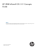
2 Overview 3PAR Storage Concepts and Terminology HP 3PAR Storage Systems include both the hardware components that physically store your data, and the software applications that manage your data. For more information about hardware platforms, see “HP 3PAR Storage System Hardware” (page 58). For more information about system software applications and features, see “HP 3PAR InForm OS Software” (page 15).
Figure 1 HP 3PAR Storage System Data Layers Physical Disks A physical diskis a hard drive mounted on a drive magazine located in an HP 3PAR Storage System drive cage. For more information about physical disks and the HP 3PAR Storage System hardware platforms, see “HP 3PAR Storage System Hardware” (page 58). Chunklets Physical disks are divided into chunklets. Each chunklet occupies contiguous space on a physical disk. On F-Class and T-Class systems all chunklets are 256 MB.
space allocation, growth increments and other logical disk parameters can be set when you create a CPG or modified later. HP 3PAR Storage Systems support the following RAID types: • RAID 0 • RAID 10 (RAID 1) • RAID 50 (RAID 5) • RAID Multi-Parity (MP) or RAID 6 For a detailed discussion of logical disks and RAID types, see “Logical Disks” (page 35). Common Provisioning Groups A Common Provisioning Group (CPG) is a virtual pool of logical disks that allocates space to virtual volumes on demand.
have a user space size at least as large as the user space of the base volume being copied, and must not be exported. For additional information on physical copies, see “Physical Copies” (page 45). NOTE: With an HP 3PAR Remote Copy Software license, physical copies can be copied from one HP 3PAR Storage System to another using Remote Copy. For additional information, see the HP 3PAR Remote Copy User’s Guide. Virtual Copy Snapshots A snapshot is a virtual copy of a base volume.
• HP 3PAR Autonomic Groups, allow domains, hosts, and volumes to be grouped into a set that is managed as a single object. Autonomic groups also allow for easy updates when new hosts are added or new volumes are provisioned. If you add a new host to the set, volumes from the volume set are autonomically provisioned to the new host without any administrative intervention. If you add a new volume or a new domain to a set, the volume or domain inherits all the rights of the set.
3PAR Thin Conversion license, and an HP 3PAR Thin Persistence license. To learn more about HP 3PAR Thin Persistence, see “Enhanced Storage Applications” (page 53). • HP 3PAR Thin Copy Reclamation Software reclaims space when snapshots are deleted from an HP Storage System. As snapshots are deleted, the snapshot space is reclaimed from a TPVV or fully-provisioned virtual volume and returned to the CPG for reuse by other volumes.
snapshot images of SQL Server databases for non-disruptive backup, rapid application recovery, and data sharing. • HP 3PAR VSS Provider for Microsoft Windows Software is a server application bundled with Recovery Manager for Microsoft Exchange and SQL Server. VSS coordinates the actions of: ◦ Database readers like the HP 3PAR Recovery Manager backup application. ◦ Database writers like Microsoft Exchange and SQL Server. ◦ Providers that create shadow copies.
3 HP 3PAR Storage System Users User Accounts In order to access an HP Storage System you must have a user account. Each InForm OS user is assigned a role, and each role is assigned a set of rights. The roles and rights assigned to the user determine which tasks the user can perform with a system. Assign roles to users based on the tasks you intend the users to perform. Eight roles are defined in the InForm OS. See Table 3 (page 19) for a description of each role.
Table 3 InForm OS User Roles (continued) User Roles Rights Assigned to Roles 3PAR AO Rights are limited to internal use by HP for Adaptive Optimization operations. 3PAR RM Rights are limited to internal use by HP for Recovery Manager operations. Local User Authentication and Authorization Users accessing the HP 3PAR Storage System with the InForm OS CLI client or Secure Shell (SSH) connections are authenticated and authorized directly on the system. These users are referred to as local users.
4 LDAP Overview The Lightweight Directory Access Protocol (LDAP) is a standard protocol for communication between LDAP clients and LDAP directory servers. Data is stored as a directory hierarchy by the server and clients add, modify, search, or remove the data. The data can be organized using standard schemas understood by clients and servers from different vendors or by an application-specific schema used only by a particular vendor or application.
Additionally for local users, during authentication, the password supplied by the user must match the password assigned when that user was initially created or modified. The rights assigned to the user during authorization are the same rights associated with the user role assigned when that user was initially created or modified. See “HP 3PAR Storage System Users” (page 19) for additional information about user roles and rights.
LDAP Authentication and Authorization As stated earlier, the user’s user name is first checked against the authentication data stored on the local system. If the user’s name is not found, the LDAP authentication and authorization process proceeds as follows: • The user’s user name and password are used to authenticate with the LDAP server. • The user’s group memberships are determined with the data on the LDAP server.
Each group to which a user is a member is compared against the mapping parameters. Mapping occurs sequentially with a group first compared to the super-map parameter. If no match is made, the group is then compared with the service-map parameter, and so on. For example, if a match is made for group A with the super-map parameter, the user belonging to group A is authorized with Super rights to the system. With this process, a user can be authenticated, but not authorized if no group membership exists.
5 HP 3PAR Virtual Domains Overview When initially setting up the HP 3PAR Storage System, the system administrator creates and assigns users with roles and rights in the system. You can create, modify, and remove a user’s access to HP 3PAR Virtual Domains Software in the system with both the HP 3PAR InForm Command Line Interface (CLI) and the HP 3PAR InForm Management Console.
Domain Type The first tier of access control is the domain to which a subset of a system’s objects belong. The objects can be assigned to a specific domain, or have no domain association. • The no domain contains objects that do not belong to any specified domains. For example, objects in an existing system that did not previously use domains do not belong to any domains. • specified domains are created by the domain administrator and contain objects specific to that domain.
An InForm OS CLI user’s default domain is the domain the user accesses at the start of each CLI session. For example, if you have Edit rights to Domains A and B and your default domain has been set to Domain A, each time you start a new CLI session you will view and work with only objects in Domain A. The user’s default domain can be set and reset at any time by the administrator.
6 Ports and Hosts Overview The HP 3PAR Storage System sees a host as a set of initiator port WWNs (World Wide Names) or iSCSI Names. Hosts that are physically connected to ports on the system are automatically detected. The Fibre Channel port WWNs and iSCSI port iSCSI Names are displayed by the user interfaces. You can also add new WWNs or iSCSI Names for unestablished host paths and assign them to a host before they are physically connected.
Port Location Formats The InForm OS CLI and the InForm Management Console display the controller node Fibre Channel, iSCSI, and Gigabit Ethernet port locations in the following format:::. For example: 2:4:1. • • • Node: Valid node numbers are 0-7 depending on the number of nodes installed in your system. When viewing a system from the rear of a cabinet: ◦ F-Class nodes are numbered 0-3 from top to bottom. ◦ T-Class nodes are numbered 0-7 from left to right, top to bottom.
Active and Inactive Hosts An active host is a host that is connected to a system port and recognized by the InForm OS. Under normal operation, an active host may have a number of volumes exported to it and therefore the host has access to those volumes. An inactive host is a host that is known to the InForm OS but is not recognized as being connected to any system port at the moment.
• VolSetAddr - Enables HPUX Volume Set Addressing (VSA). • SoftInq - Enables inquiry data formats for hosts such as Egenera and NetApp. • NACA - Enables Normal Auto Contingent Allegiance (NACA) bit for AIX. • SESLun - Enables iSCSI Enclosure Services (SES) LUN ID 254 for Host Explorer agent support. NOTE: Each host connected to the system must use a host persona with the iSCSI Enclosure Services LUN (SESLun) enabled, or the Host Explorer agent cannot communicate with the system.
WWN or iSCSI name to a host. With Host Explorer agents running, the system automatically groups WWNs or iSCSI names for the host together, assisting with creating the host. The Host Explorer agent collects the following information and sends it to the system: • Host operating system and version. • Fibre Channel and iSCSI HBA details. • Multipath driver and current multipath configuration. • Cluster configuration information. You can install the Host Explorer agent from the HP 3PAR Host Explorer CD.
7 Chunklets Overview Physical disks are divided into chunklets. When a physical disk is admitted to the system it is divided into chunklets that become available to the system. Some chunklets are used by logical disks and other chunklets are designated as spares to hold relocated data during a disk failure or during maintenance procedures. Creating, moving, and removing chunklets and spares can only be performed with the HP 3PAR InForm Command Line Interface (CLI).
• For automatic relocations, the system uses up a maximum of one disk worth of chunklets per system node. • When selecting a target chunklet for relocation, the system attempts to identify a local spare chunklet, a local free chunklet, a remote spare chunklet, and then finally a remote free chunklet. NOTE: Local chunklets are chunklets on disks whose primary path is connected to a node that owns the logical disk containing the chunklets being relocated.
8 Logical Disks Overview A Logical Disk (LD) is a collection of physical disk chunklets arranged as rows of RAID sets. Each RAID set is made up of chunklets from different physical disks. Logical disks are pooled together in Common Provisioning Groups (CPGs) which allocate space to virtual volumes. Creating CPGs maps out the data layout parameters for the creating logical disks. Logical disks are created automatically by the system when virtual volumes are created from CPGs.
failures. When the destination logical disks become available again, the system automatically writes the preserved data from the preserved data logical disks to the destination logical disks. • Administration volume logical disks provide storage space for the admin volume, a single volume created on each system during installation. The admin volume is used to store system administrative data such as the system event log.
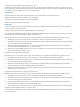
Figure 4 Data Striped Across RAID 1 Sets on a RAID 10 Logical Disk RAID 5 and 50 On a RAID 50 logical disk, data is striped across rows of RAID 5 sets. A RAID 5 set, or parity set, must contain at least three chunklets. A RAID 5 set with three chunklets has a total of two chunklets of space for data and one chunklet of space for parity. RAID 5 set sizes with between 3 and 9 chunklets are supported. The data and parity steps are striped across each chunklet in the set.
Figure 5 Data Striped Across RAID 5 Sets on a RAID 50 Logical Disk RAID Multi-Parity On a RAID Multi-Parity (MP) or RAID 6 logical disk, data is striped across rows of RAID MP sets. A RAID MP set, or double-parity set, must contain at least 8 chunklets. A RAID MP set with 8 chunklets has a total of 6 chunklets of space for data and 2 chunklets of space for parity. RAID MP set sizes of 8 and 16 chunklets are supported. The data and parity steps are striped across each chunklet in the set.
Figure 6 Data Striped Across RAID MP Sets on a RAID MP Logical Disk Logical Disk Size and RAID Types A logical disk is a collection of physical disk chunklets arranged as rows of RAID sets. On F-Class and T-Class systems all chunklets are 256 MB. On P10000 systems all chunklets are 1 GB. All systems round up so that the logical disk size is divisible by the size of one chunklet, either 1 GB or 256 KB. The total size of the logical disk is determined by the number of data chunklets in the RAID set.
9 Common Provisioning Groups Overview A Common Provisioning Group (CPG) creates a virtual pool of logical disks that allows up to 4,095 virtual volumes to share the CPG's resources and allocates space on demand. You can create fully-provisioned virtual volumes and Thinly-Provisioned Virtual Volumes (TPVVs) that draw space from the CPG's logical disk pool. CPGs enable fine-grained, shared access to pooled logical capacity.
Growth Increment As volumes that draw from a CPG require additional storage, the system automatically creates additional logical disks according to the CPG's growth increment. The default growth increment is fixed at 32 GB, but the minimum growth increment varies according to the number of controller nodes in the system and ranges from 8 GB for a two-node system to 32 GB for a four-node system (Table 5 (page 41)).
of the system. For example, on a 4 TB system it is possible to create a CPG with a 5 TB growth limit. Likewise, it is possible to create five CPGs, each with a 2 TB growth limit, etc. In addition, volumes that draw from a CPG can only use the space available to that CPG based on the CPG's logical disk parameters.
10 Virtual Volumes Overview Volumes draw their resources from Common Provisioning Groups (CPGs), and volumes are exported as Logical Unit Numbers (LUNs) to hosts. Virtual volumes are the only data layer visible to hosts. You can create physical copies or virtual copy snapshots of virtual volumes for use if the original base volume becomes unavailable. Before creating virtual volumes, you must first create CPGs to allocate space to the virtual volumes.
For greater administrative flexibility, you can provision the virtual volume’s user space and snapshot space from the same or different CPGs. If the virtual volume’s user space and snapshot space are on a different CPGs, the user space remains available to the host if the CPG containing the snapshot space becomes full. To save time by not repeating tasks, you can create many identical virtual volume’s at one time.
TPVV Warnings and Limits The TPVV volume size limit is 16 TB. When creating a TPVV, you have the option to set an allocation warning threshold and an allocation limit threshold. • allocation warning threshold: For volumes capable of allocating space on demand, the user-defined threshold at which the system generates an alert. This threshold is a percentage of the volume's virtual size, the size that the volume presents to the host.
causes them to lose synchronization with each other, which is corrected by resynchronizing the two volumes as described in the InForm OS CLI Administrator’s Manual and the InForm OS Management Console Online Help. No special license is required to create a physical copy of a volume. Physical copies can be created and managed in groups to reduce the number of management tasks.
only create read-only copies of a base volume. See Figure 7 (page 47) for an example of alternating read-only and read/write virtual copy relationships. Figure 7 Alternating Read-only and Read/Write Virtual Copies See Figure 8 (page 47) for a more complex example of the possible relationships between a parent base volume and its virtual copies.
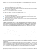
Figure 9 Snapshot Tree The relationships between the virtual copies derived from a base volume can be represented as a tree. In the example in Figure 9 (page 48), the base volume BaseVV is the starting point. In this example, each new virtual copy of the original has its name incremented by 1. Each copy of a copy has an additional level added to its name: in this example, the first copy of S1 is S1_0, and a copy of S1_0 is S1_0_0.
that the snapshot was created by copying another virtual volume. The parent relationship refers to the internal organization of the administration space. The parent volume contains information needed to reconstruct the snapshot represented by the child volume. A parent volume can have a creation date after that of its child if the parent volume was modified. The parent relationship is useful for two reasons: • Understanding the performance consequences of virtual copies.
• Port presents allows any host on a specific port to see the volume. • Matched set allows only a specific host on a specific port to see the volume. Host Sees A host sees VLUN template allows only a particular host connected to any port to see a virtual volume. The system makes the virtual volume visible as a LUN to all the host’s WWNs, regardless of which controller node port the WWNs appear on. If the host has more than one WWN, active VLUNs are created for each host WWN.
11 Reclaiming Unused Space Overview The InForm OS space consolidation features allow you to change the way that virtual volumes are mapped to logical disks in a Common Provisioning Group (CPG). Moving virtual volume regions from one logical disk to another enables you to compact logical disks, and free up disk space so that it can be reclaimed for use by the system. For more information about virtual volumes, see “Virtual Volumes” (page 43).
Compacting a CPG allows you to reclaim space from a CPG that has become less efficient in space usage from creating, deleting, and relocating volumes. Compacting consolidates logical disk space in CPGs into as few logical disks as possible. Compacting CPGs can be performed with both the HP 3PAR InForm OS Command Line Interface (CLI) and the HP 3PAR InForm Management Console.
12 Enhanced Storage Applications Overview HP offers several enhanced storage features for managing data and improving system performance. Optional features require you to purchase a separate license. You can use the HP 3PAR OS Command Line Interface (CLI) and the HP 3PAR Management Console to view the licenses currently enabled on your systems. For a list of default HP 3PAR OS Software Suite features and optional features, see “HP 3PAR InForm OS Software” (page 15).
There are several ways Dynamic Optimization may improve system performance: • Volume layout changes after hardware upgrades. Existing virtual volumes only take advantage of resources that were present at the time of volume creation. When a system is upgraded by adding nodes, cages, or disks, the original volume and logical disk layouts may no longer be optimal. Changing the layout of a virtual volume enables volumes to take full advantage of new system resources.
If the performance of one or more physical disks degrades, the throughput of the logical disks is reduced and the entire system performance may decline. There are two general reasons why a physical disk may have degraded performance: • The physical disk has reached its maximum throughput due to an unbalanced load. A disk in this state typically has unusually high average service times when compared to other disks. • The physical disk is a bad disk.
Zeroing Unused Space Use a host application to write zeros to the allocated but unused volume space. F-Class, T-Class, and P10000 Storage Systems detect and discard the zeros during the volume copy operation. Creating a Physical Copy After writing zeros to the allocated but unused space, the source volume is ready for the final phase of conversion. You create a TPVV physical copy of the source volume to convert the source volume to a TPVV.
HP 3PAR Virtual Lock Software HP 3PAR Virtual Lock Software is an optional feature that enforces the retention period of any volume or copy of a volume. You must purchase the HP 3PAR Virtual Lock license to use this feature. Locking a volume prevents the volume from being deleted intentionally or unintentionally before the retention period elapses. You can use Virtual Lock to specify the retention period for each volume or copy of a volume.
13 HP 3PAR Storage System Hardware Overview HP 3PAR Storage Systems are available in a variety of hardware configurations. Different models address different levels of storage capacity and anticipated growth requirements. All models use the InForm® Operating System (OS). Hardware monitoring and configuration tasks can be performed with both the HP 3PAR InForm Command Line Interface (CLI) and the HP 3PAR InForm Management Console.
Figure 12 P10000 Rear View Physical Disks A physical disk is a hard drive mounted on a drive magazine or module located in drive cages in HP 3PAR Storage Systems. There are three types of physical disks: Fibre Channel (FC), Near Line (NL) and Solid State Drives (SSD). In DC4 drive cages, each drive magazine holds four disks numbered 0 through 3 from the rear to the front of the magazine. The DC4 drive cages contain a maximum of ten drive magazines for a maximum of 40 physical disks in each drive cage.
Figure 14 DC3 Drive Magazine Module with One Physical Disk Drive Cage Models • The T-Class and P10000 systems contain both DC4 drive cages. The DC4 is a 40 disk, 4 Gbps drive cage. • The F-Class systems only contain DC3 drive cages. The DC3 is a 16 disk, 4 Gbps drive cage. DC4 Drive Cages and Ports and Cabling The DC4 drive cages house ten drive bays numbered 0 through 9. Each drive bay accommodates a single drive magazine that holds four disks.
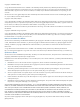
Figure 15 DC4 Drive Cage NOTE: Daisy chaining is not supported for the DC4 drive cages. DC3 Drive Cage and Ports and Cabling The DC3 drive cage contains 16 drive bays at the front, each accommodating the appropriate plug-in drive magazine module. The 16 drive bays are arranged in four rows of four drives. Figure 16 (page 61) shows the front view of a DC3 drive cage.
Figure 17 DC3 Drive Cage (Rear View) Controller Nodes System controller nodes use Fibre Channel, Gigabit Ethernet, and iSCSI ports to connect the storage sever to your network, host computers, storage sever components, and to other systems. Inside each controller node there are slots for network adapters, control cache DIMMs, and data cache DIMMs. The number of controller nodes in each system, and the type and number of network adapters is configurable.
NOTE: For information about port location and numbering, see “Port Location Formats” (page 29). NOTE: For information about how to view the control cache DIMM and data cache DIMM configurations for each controller node, see the HP 3PAR HP 3PAR InForm OS CLI Administrator's Manual and InForm OS Management Console Online Help. For information about memory expansion, contact your HP representative.
A controller node takes on the number of the bay that it occupies in the system backplane, as shown in Figure 19 (page 64). Figure 19 T-Class Controller Node Numbering F-Class Controller Node Numbering The F-Class systems contains two or four nodes per system. Controller nodes are numbered from top to bottom node 0 and node 1 for a two node system, and node 0- 3 for a four node system. See Figure 20 (page 65) for an example of controller node numbering in an F-Class system.
Figure 20 F-Class Controller Node Numbering Controller Nodes 65
14 InForm OS SNMP Infrastructure Overview In addition to managing the system with the InForm Management Console and the InForm OS CLI, the HP 3PAR InForm OS includes an SNMP agent that allows you to perform some basic management functions via network management software running on a management station. These SNMP management functions require that you have SNMP management software not provided by HP.
Standard Compliance The HP 3PAR SNMP agent supports the following standards: • SNMPv2c This version refers to a widely used administrative framework for SNMPv2, also known as “community-based SNMPv2.” Although this version includes SNMPv2 enhancements like notification and GETBULK requests, it still relies on the SNMPv1 community concept for security. • Standard Management Interface-v2 (SMIv2) This standard specifies the format of the MIB. The HP 3PAR MIB definition uses SMIv2 conventions.
Table 8 MIB-II Objects Supported by the SNMP Agent (continued) Object Descriptor Description Access sysName Name of the system. This helps to Read-only identify the storage system. This name cannot be set via SNMP. sysLocation User-defined system location. For example: Building 1, room 4, rack 3. Read/write Exposed Objects The 3PAR SNMP agent supports MIB-II system group objects. This section describes each of those objects in detail.
Default value: Please provide contact information such as name, phone number, and e-mail address Description: Specifies the name of a person or group responsible for maintaining the storage. This value can be changed via the manager at any time. System Name Access: Read-only MIB definition: sysName Data type: Display string (max. 255 characters) Default value: None Description: Indicates the system name, which is set during initialization and setup of the system.
Table 9 Contents of the alertNotify trap (continued) Object Descriptor Description Access timeOccurred Time the alert or alert state change Read-only occurred, in DDD mmm dd hh:mm:ss ZZZ yyyy format (for example: Mon, Jan 01 12:30:34 PST 2005). id Alert ID. The alert ID uniquely Read-only identifies an outstanding alert on some object within the system. Alert IDs are automatically generated by the InForm OS and increment when a new alert on a new object is detected.
NOTE: If you receive a trap with messageCode == 1245186, this is to notify you that an alert has changed state. In order to find out which alert has changed state, you must extract the alert ID from the id trap field. An alert status change event is not an alert. It notifies you that an alert has changed status (e.g., from New to Resolved by System). The following example shows an alertNotify trap translated from an alert status change event: sysUpTime.0:0 hours, 5 minutes, 26 seconds. snmpTrapOID.0:.iso.
15 The HP 3PAR InForm OS CIM API Overview This chapter describes the HP 3PAR InForm OS CIM Application Programming Interface (API), HP’s industry-standard API based on SNIA’s Storage Management Initiative Specification (SMI-S). For detailed information about the HP 3PAR InForm OS CIM API, refer to the HP 3PAR CIM API Programming Reference. CAUTION: The CIM API is not part of the evaluated Common Criteria storage system configuration and should not be used when operating in Common Criteria mode.
This protocol is defined by the following specifications: • Specification for the Representation of CIM in XML Defines a standard for the representation of CIM elements and messages in XML, written in Document Type Definition (DTD). • CIM Operations over HTTP Defines a mapping of CIM Messages onto HTTP that allows implementations of CIM to interoperate in an open, standardized manner. It uses the CIM XML DTD that defines the XML Schema for CIM objects and messages.
Glossary Access Guard A software component that provides volume security at logical and physical levels. Access Guard is part of the HP 3PAR OS Software Suite. active VLUN The pairing of a virtual volume and a LUN so the host can access its virtual volume and I/O writes can be saved to the virtual volume. The VLUN parameters determine whether a virtual volume is expressed as an active VLUN. VLUNs that are not active will not communicate with the storage system.
controller node An individual device that works with other controller nodes to cache and manage data in a system and to provide hosts with a coherent, virtualized view of the storage system. controller node chassis An enclosure that houses all the controller nodes of a system. copy data Data that occupies the snapshot data space (virtual copy space) on a virtual volume. copy size The amount of snapshot data space (the logical disk space reserved for snapshots) in a virtual volume.
FC-AL Fibre Channel Arbitrated Loop. A fast serial bus interface standard used to connect storage devices to servers. Fibre Channel adapter A Fibre Channel PCI host bus adapter (HBA) located in a controller node. The Fibre Channel adapter connects a controller node to a host or to a drive chassis.
During loop initialization, the nodes present on the arbitrated loop identify themselves and acquire addresses on the loop. No data can be transferred on an arbitrated loop until initialization completes. logging Temporarily saving data to logging logical disks when physical disks are out of service (due to failure or during replacement procedures). logging LD Logging logical disk. A logical disk used for logging.
primary and secondary paths are not user configurable and are determined by drive magazine placement. promote For physical copies: to break the association between a physical copy and a base volume by changing the physical copy into an independent base volume. For virtual copies: to copy the changes from a virtual copy back onto the base volume, therefore overwriting the base volume with the virtual copy. rack The EIA-standard rack within a cabinet that holds the components of a system.
snapshot A virtual or physical copy of a virtual volume. snapshot administration space The space on a virtual volume that is used to track changes to the data from the time that a snapshot of a virtual volume was created. source volume The virtual volume from which a copy is made. spare chunklet A chunklet that is reserved for use in case of a failure in the system.
Volumes, no storage is actually allocated to user space, so the user space represents the volume's virtual size. virtual copy A snapshot created using the copy-on-write technique. virtual copy policy Policy that determines the course of action to take when a volume's snapshot administration space or snapshot data space becomes depleted. virtual size The size that the volume presents to the host. For standard base volumes, the virtual size is equal to the user space.
Index A Active Directory Kerberos server, 21 Active Directory LDAP, 21 Active Directory LDAP server, 21 admin volume, 44 advisories, conventions, 11 alerts when spare and free chunklets are used up, 34 allocation limit, 45 allocation warning, 45 authentication, 21 B base volumes retrieval time affected by distance from, 49 virtual copy tree relationships, 48 C cautions, about, 11 chunklets, 33 free, defined, 33 conventions advisories, 11 conventions, typographical, 11 copy-on-write function, 47 D default
S schemas, 21 simple binding, 23 snapshots creation rules, 48 stale definition, 49 tree view of, 48 SNMP (Simple Network Management Protocol), 66 T typographical conventions, 11 U user interfaces, 10 user rights in domains, 26 V virtual columes naming conventions, 48 virtual copies stale definition, 49 virtual volumes base retrieval time affected by distance from, 49 copy-of relationships, 48 definition, 51 deleting limitations when, 48 mapping, definition, 51 parent relationships, 48 performance consequ