
HP 3PAR F-Class, T-Class, StoreServ 10000 Storage Troubleshooting Guide (QL226-96953, May 2013)

Controller Node Numbering
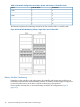
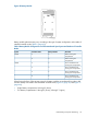
A storage system may contain two to eight controller nodes per system configuration. The controller
node chassis is located at the rear of the storage cabinet.
From the rear of the storage cabinet, component numbering starts with zero (0) from left to right.
For example, the node in the lower left position is identified as Node 0 and the adjacent node
(right) is identifed as Node 1.
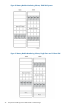
With a larger controller node chassis that supports a maximum of eight controller nodes, the
orientation of the lower and upper controller nodes becomes inverted. The controller node located
in upper right corner of a 10800 is identified as controller node 7. If there are empty bays, install
filler panels to protect the node chassis.
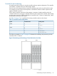
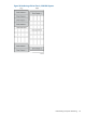
Use Table 10 (page 47) as a guideline for loading controller nodes into the chassis.
Table 10 Controller Node Loading Order
Loading OrderController NodesSystem
0, 1210400
0, 1, 2, 34
0, 1210800
0, 1, 4, 54
0, 1, 4, 5, 2, 36
0, 1, 4, 5, 2, 3, 6, 78
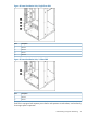
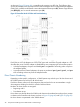
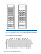
The following example in Figure 12 (page 47) illustrates the numbering and positioning of each
controller node in a cabinet.
Figure 52 Numbering and Positioning of Controller Nodes, Rear View
Understanding Component Numbering 47