
HP 3PAR F-Class, T-Class, StoreServ 10000 Storage Troubleshooting Guide (QL226-96953, May 2013)
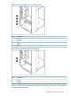
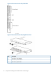
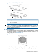
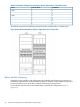
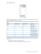
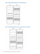
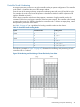
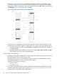
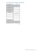
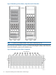

Figure 49 Battery Module
Battery module placement may vary according to the type of system configuration and number of
installed controller nodes (Table 2 (page 45)).
Table 9 Battery Module Configuration and Placement Based Upon System and Number of Controller
Nodes
PlacementBattery ModulesController NodesSystem
Below Cooling Fan
Compartment
2210400
Below Cooling Fan
Compartment
44
Above and Below Each
Cooling Fan Compartment
2210800
Above and Below Each
Cooling Fan Compartment
44
Above and Below Each
Cooling Fan Compartment
66
Above and Below Each
Cooling Fan Compartment
88
When facing the front of the storage system, the battery modules are numbered from right to left
and are directly connected to the associated controller node (Figure 50 (page 46) and Figure 51
(page 46)).
• Single battery compartment: 0 through 3 (lower)
• Two battery compartments: 0 through 3 (lower); 4 through 7 (upper)
Understanding Component Numbering 45