
HP 3PAR F-Class, T-Class, StoreServ 10000 Storage Troubleshooting Guide (QL226-96953, May 2013)
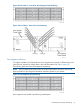
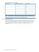
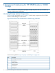
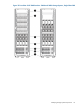
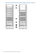
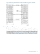
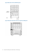
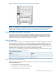
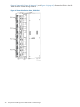

Figure 40 Placement of the Service Processor, 3–Phase PDU Systems
NOTE: For both 10400 and 10800 Storage systems, the SP is located below the controller node
chassis (Figure 38 (page 38), “Placement of the Service Processor, Single Phase PDU Systems”
(page 38) and “Placement of the Service Processor, 3–Phase PDU Systems” (page 39)).
Understanding Component Numbering
Because of the large number of possible storage system configurations, HP has standardized
component placement and internal cabling to simplify installation and maintenance. System
components are placed in the cabinet according to the principles outlined in this section and
numbered according to their order and location in the cabinet.
Cabinet Numbering
The 2M storage system cabinet is an EIA-standard rack and houses the storage system components.
A storage system can be housed in a single or multiple cabinets. When multiple cabinets are
required, the first cabinet (known as the controller node cabinet) holds the storage system node
chassis populated with controller nodes. Any additional cabinets, or drive chassis cabinets, store
the additional drive chassis that do not fit into the controller node cabinet.
Table 7 (page 101) describes the pattern for cabinet numbering in multi-cabinet storage systems
and for operating sites with multiple systems.
Table 7 Cabinet Numbering
NumberCabinet
C0Controller node cabinet
C1, C2, C3...C5Drive chassis cabinets connecting to the first node cabinet
Power Distribution Unit Numbering
Each cabinet contains one of the following configurations. Numbers for PDUs are assigned beginning
with 0, from bottom to top.
• four 3PAR PDUs mounted along the side
• four Single-Phase PDUs mounted at the bottom
• two 3–Phase PDUs mounted at the bottom
Understanding Component Numbering 39