53-1001216-01 March 9, 2009 Fabric OS Documentation Addendum Supporting Fabric OS v6.1.
Copyright © 2009 Brocade Communications Systems, Inc. All Rights Reserved. Brocade, Fabric OS, File Lifecycle Manager, MyView, and StorageX are registered trademarks and the Brocade B-wing symbol, DCX, and SAN Health are trademarks of Brocade Communications Systems, Inc., in the United States and/or in other countries. All other brands, products, or service names are or may be trademarks or service marks of, and are used to identify, products or services of their respective owners.
Contents About This Document In this chapter . . . . . . . . . . . . . . . . . . . . . . . . . . . . . . . . . . . . . . . . . . . vii How this document is organized . . . . . . . . . . . . . . . . . . . . . . . . . . . . vii Supported hardware and software . . . . . . . . . . . . . . . . . . . . . . . . . . vii What’s new in this document . . . . . . . . . . . . . . . . . . . . . . . . . . . . . . . viii Document conventions . . . . . . . . . . . . . . . . . . . . . . . . . . . . . . . . . . . .
Chapter 2 Fabric OS Command Reference In this chapter . . . . . . . . . . . . . . . . . . . . . . . . . . . . . . . . . . . . . . . . . . . . 9 New commands in Fabric OS v6.1.2_cee . . . . . . . . . . . . . . . . . . . . . . 9 Modified commands . . . . . . . . . . . . . . . . . . . . . . . . . . . . . . . . . . . . . . 17 Notes . . . . . . . . . . . . . . . . . . . . . . . . . . . . . . . . . . . . . . . . . . . . . . . . . . 26 Command RBAC permissions and AD types . . . . . . . . . . . . . . . . . . .
Chapter 5 Web Tools Administrator’s Guide In this chapter . . . . . . . . . . . . . . . . . . . . . . . . . . . . . . . . . . . . . . . . . . . 83 New information . . . . . . . . . . . . . . . . . . . . . . . . . . . . . . . . . . . . . . . . . 83 Terms and concepts . . . . . . . . . . . . . . . . . . . . . . . . . . . . . . . . . . . . . . 84 Search, Export, and Copy options . . . . . . . . . . . . . . . . . . . . . . . . . . . 84 8000 switch view . . . . . . . . . . . . . . . . . . . . . . . . . . . . .
vi Fabric OS Documentation Addendum 53-1001216-01
About This Document In this chapter • How this document is organized . . . . . . . . . . . . . . . . . . . . . . . . . . . . . . . . . . vii • Supported hardware and software. . . . . . . . . . . . . . . . . . . . . . . . . . . . . . . . . vii • What’s new in this document . . . . . . . . . . . . . . . . . . . . . . . . . . . . . . . . . . . . . viii • Document conventions . . . . . . . . . . . . . . . . . . . . . . . . . . . . . . . . . . . . . . . . . . viii • Additional information . . . . . . . . . . .
What’s new in this document This is a new document. Document conventions This section describes text formatting conventions and important notice formats used in this document.
Notes, cautions, and warnings The following notices and statements are used in this manual. They are listed below in order of increasing severity of potential hazards. NOTE A note provides a tip, guidance or advice, emphasizes important information, or provides a reference to related information. ATTENTION An Attention statement indicates potential damage to hardware or data.
For additional Brocade documentation, visit the Brocade Web site: http://www.brocade.com Release notes are available on the Brocade Connect Web site and are also bundled with the Fabric OS firmware. Other industry resources For additional resource information, visit the Technical Committee T11 Web site. This Web site provides interface standards for high-performance and mass storage applications for Fibre Channel, storage management, and other applications: http://www.t11.
• Brocade 5000—On the switch ID pull-out tab located on the bottom of the port side of the switch • • • • Brocade 7600—On the bottom of the chassis Brocade 48000—Inside the chassis next to the power supply bays Brocade DCX—On the bottom right on the port side of the chassis Brocade DCX-4S—On the bottom right on the port side of the chassis, directly above the cable management comb. 3. World Wide Name (WWN) Use the wwn command to display the switch WWN.
xii Fabric OS Documentation Addendum 53-1001216-01
Chapter 1 Fabric OS Administrator’s Guide In this chapter The updates in this chapter are for the Fabric OS Administrator’s Guide, part number: 53-1000598-04. • Fabric OS support for the Brocade 8000. . . . . . . . . . . . . . . . . . . . . . . . . . . . . • Chapter 1, Getting Started . . . . . . . . . . . . . . . . . . . . . . . . . . . . . . . . . . . . . . . . • Chapter 2, Managing User Accounts . . . . . . . . . . . . . . . . . . . . . . . . . . . . . . . .
1 Chapter 1, Getting Started In addition, some Fabric OS features are supported on the Brocade 8000, but are supported only on the FC ports and not on the CEE ports. Table 1 lists the Fabric OS features and indicates whether the feature is supported, supported only on the FC ports, or not supported.
Chapter 2, Managing User Accounts 1 Chapter 2, Managing User Accounts Under the heading “With a recovery string” on page 55, add the Brocade 8000 to the other switch models. Under the heading “Without a recovery string” on page 57, add the Brocade 8000 to the other switch models. Chapter 3, Configuring Standard Security Features Under the heading “Listener applications” on page 94, add the Brocade 8000 to the other switch models in the last column of Table 19.
1 Chapter 8, Administering Advanced Zoning Under the heading “Overview of the firmware download process on switches” on page 178, change the first sentence to the following: The following list describes the default behavior after you enter the firmwareDownload command (without options) on Brocade 200E, 300, 4012, 4016, 4018, 4020, 4024, 4100, 4900, 5000, 5100, 5300, 7500, 7600, and 8000 switches: On page 179 add the Brocade 8000 to the list of switch models in the procedure heading at the top of the page.
Chapter 14, Administering NPIV 1 Chapter 14, Administering NPIV Under the heading “Enabling and disabling NPIV” on page 333, change the Note to the following: NOTE The FC10-6 port blade and the CEE ports on the Brocade 8000 do not support NPIV. Chapter 17, Administering Advanced Performance Monitoring In Table 91 on page 402, add the Brocade 8000 to the last row in the table, and add a footnote.
1 Chapter 18, Administering Extended Fabrics Under the heading “Top Talker monitors” on page 409, change the note to the following: NOTE Initial stabilization is the time taken by a flow to reach the maximum bandwidth. This time varies depending on the number of flows in the fabric and other factors. The incubation period can be up to 14 seconds in the Brocade DCX and up to 82 seconds in the Brocade 4100, 4900, 5000, 5100, 5300, 7500, 7500E, 7600, 8000, and 48000.
Chapter 19, Administering ISL Trunking 1 Chapter 19, Administering ISL Trunking On page 430 change the second paragraph after Figure 47 to the following: Connections between Brocade 300, 4020, 4024, 4044, 4100, 4900, 5100, 5300, 7500, 7600, 8000 switches, the Brocade 48000 using the FC4-16/32/48, FC4-16IP, FA4-18, FC8-16/32/48, and FR4-18i blades, and the Brocade DCX using the FC8-16/32/48 and FR4-18i blades support these advanced features: On page 430 change the note in the middle of the page to the foll
1 Appendix A, Configuring the PID Format In Table 100 on page 441, change the entry for FC8-48 and FC4-48C blades to the following: Category Description FC4-48C blade On the FC4-48C blade F_Port trunking is supported only on ports 0 - 15. Under the heading “Setting up F_Port trunking” on page 443, change the fourth sentence in the first paragraph to the following: The Brocade 300, 5100, 5300, and 8000 platforms support a trunk group with up to eight ports.
Chapter Fabric OS Command Reference 2 In this chapter • New commands in Fabric OS v6.1.2_cee . . . . . . . . . . . . . . . . . . . . . . . . . . . . 9 • Modified commands . . . . . . . . . . . . . . . . . . . . . . . . . . . . . . . . . . . . . . . . . . . . 17 • Notes . . . . . . . . . . . . . . . . . . . . . . . . . . . . . . . . . . . . . . . . . . . . . . . . . . . . . . . . 26 • Command RBAC permissions and AD types . . . . . . . . . . . . . . . . . . . . . . . . . 27 New commands in Fabric OS v6.
2 cmsh TenGigabitEthernet TenGigabitEthernet TenGigabitEthernet TenGigabitEthernet TenGigabitEthernet TenGigabitEthernet TenGigabitEthernet TenGigabitEthernet TenGigabitEthernet TenGigabitEthernet TenGigabitEthernet TenGigabitEthernet TenGigabitEthernet TenGigabitEthernet TenGigabitEthernet TenGigabitEthernet TenGigabitEthernet TenGigabitEthernet TenGigabitEthernet switch:admin>#exit 0/5 unassigned administratively down down 0/6 unassigned administratively down down 0/7 unassigned administratively down d
FCoE 2 FCoE Manages and displays FCoE configuration. Synopsis fcoe --cfgshow [port] fcoe --disable port fcoe --enable port fcoe --loginshow port fcoe --fcmapset -vlan vid fcmapid fcoe --fcmapunset -vlan vid fcoe --fipcfg -advintvl intvl fcoe --fipcfgshow fcoe --resetlogin [-teport slot/port | -device wwn ] fcoe --help Description Use this command to configure and display the status of FCoE Ports, FCoE Initialization Protocol (FIP), and FCMAP settings.
2 FCoE --fipcfg -advintvl intvl Examples Configures FIP multicast advertisement intervals. Specifies the interval in seconds. The minimum interval value is 0 and the maximum value is 300. A value of 0 cancels the previous advertisement interval value. A value of 1 to 300 is valid for changing the interval. --fipcfgshow Displays FIP configurations. --resetlogin Clears the logins that occurred through a front end port or from a device specified by the Enode's VN_Port WWN.
fcoeLoginCfg 2 fcoeLoginCfg Manages or displays the FCoE login configuration.
2 fcoeLoginCfg --disable Examples Disables the FCoE login configuration management on the switch. This allows unrestricted login on Enode V_Ports.
fcoeLoginGroup 2 fcoeLoginGroup Creates and manages FCoE login group configuration. Synopsis fcoelogingroup --create lgname -self |-switch swwn [-allow-all | member; member;…] fcoelogingroup --delete lgname fcoelogingroup --add lgname member; member;… [-port port] fcoelogingroup --remove lgname wwn fcoelogingroup --rename lgname newlgname fcoelogingroup --help Description Note Operands Use this command to create or modify the FCoE login management configuration fabric-wide.
2 fcoeLoginGroup lgname Specifies the name of the login group from which VN_Port devices are to be removed. wwn Identifies the WWN of the VN_Port. The WWN must be specified in hex format as xx.xx.xx.xx.xx.xx.xx.x. Only specified members are allowed to log into the switch. --rename Examples Renames the specified login group.
Modified commands 2 Modified commands Replace the following modified commands in the Fabric OS Command Reference for Fabric OS v6.1.1 (53-1000599-03) systemVerification Runs a suite of diagnostic tests on a switch or a chassis. Synopsis Description systemverification [-parameters | -short ][-unit id] Use this command to run a comprehensive, system-wide test on a switch or a chassis. The command initiates a burn-in run on all slots in a multi-bladed system.
2 systemVerification are not specified, the run uses the previously stored values. This option does not perform a burninErrClear operation prior to starting the testing. Examples -short Sets the burn-in parameters that control the number of frames to 1. The primary use for this command is software regression testing, or quick validation that all hardware is operational. The shorter test cycle does not have enough time to detect intermittent errors.
supportShow 2 supportShow Displays switch information for debugging purposes. Synopsis Description supportshow [[slotnumber/]portnumber1-portnumber2] [lines] Use this command to display support information from groups of preselected Fabric OS and Linux commands and other support and debugging information. You can specify the range of ports for which to display this information.
2 supportShow portnumber1-portnumber2 Specifies the range of ports for which to display supportShow information. If a port range is not specified, the command displays information for all ports. lines Examples Specifies the number of lines for the portLogDump output. This parameter is valid only with the slotnumber/portnumber parameters.
supportShow 000000 07:32:30.131 FCPH write 0 40 00fffffd,00fffffd,00000000,00000000,00 000000 07:32:30.131 FCPH seq 0 28 00300000,00000000,00000834,00020182,00 000000 07:32:30.131 PORT Tx 0 40 07:32:30.131 PORT Rx 0 0 07:32:41.887 PORT Rx 0 40 07:32:41.887 PORT Tx 0 0 07:32:41.
2 supportShowCfgDisable supportShowCfgDisable Disables a group of commands under the supportShow command. Synopsis supportshowcfgdisable os | exception | port | fabric | services | security | network | portlog | systemextend | filter | perfmon | ficon | iswitch | asic_db |iscsi | ag | dce_hsl Description Use this command to disable a group of commands under the supportShow command. Use the supportShowCfgEnable command to enable groups of commands.
supportShowCfgEnable 2 supportShowCfgEnable Enables a group of commands to be displayed under the supportShow command. Synopsis Description Note Operands Examples supportshowcfgenable os | exception | port | fabric | services | security | network | portlog | system | extend | filter | perfmon | ficon | iswitch | asic_db |ag | dce_hsl Use this command to enable a group of commands to be displayed under the supportShow command. Use the supportShowCfgDisable command to disable groups of commands.
2 supportShowCfgShow supportShowCfgShow Displays the groups of commands enabled for display by the supportShow command. Synopsis supportshowcfgshow Description Use this command to display the groups of commands enabled for display by the supportShow command. Use the supportShowCfgEnable and the supportShowCfgDisable commands to modify which groups are displayed. Note The execution of this command is subject to Virtual Fabric or Admin Domain restrictions that may be in place.
switchShow 2 switchShow The switchShow command should be modified as follows: 1. Add the following text to the Description section: “On the Brocade 8000, the Proto column identifies the FCoE ports of the switch. For all FcoE ports, the speed is 10 Gbps. The default configuration of an FCoE port in Fabric OS v6.1.2_cee is an F_Port configuration. After a successful reboot SwitchShow displays all FCoE ports as online. For each FCoE port, the FCoE controller WWN is shown.” 2.
2 Notes Notes Add the following notes to the Notes section of the commands listed below and their associated man pages: portDisable This command is not supported on FCoE ports. Use fcoe --disable. portEnable This command is not supported on FCoE ports. Use fcoe --enable. PortCfg* The Fabric OS port configuration commands are not supported on FcoE ports. Use fcoe --cfg to configure FCoE ports. portCfgSpeed Speed configuration is not applicable to FcoE ports.
Command RBAC permissions and AD types 2 Command RBAC permissions and AD types Refer to Table 1 for the RBAC and Admin Domain availability of new Fabric OS v6.1.2_cee commands.
2 28 Command RBAC permissions and AD types Fabric OS Documentation Addendum 53-1001216-01
Chapter 3 Fabric OS Message Reference In this chapter The updates in this chapter are for the Fabric OS Message Reference, part number: 53-1000600-03. Replace and update the chapters as described in the following sections: • Updates to chapter 1, Introduction to System messages. . . . . . . . . . . . . . . • New chapter, ANV System Messages. . . . . . . . . . . . . . . . . . . . . . . . . . . . . . . • New chapter, CEE CONFIG System Messages . . . . . . . . . . . . . . . . . . . . . . . .
3 Updates to chapter 1, Introduction to System messages 2009/02/10-14:13:34, [SS-1001], 87, SLOT 6/1 | FFDC | CHASSIS, WARNING, ESNSVT_DCX, supportSave's upload operation to host IP address aborted 2009/02/10-15:44:51, [SEC-1203], 89, SLOT 6 | FFDC | FID 128, INFO, ESNSVT_DCX, Login information: Login successful via TELNET/SSH/RSH. IP Addr:168.159.16.
Updates to chapter 1, Introduction to System messages 3 TABLE 3 System Message Field Description (Continued) Example Variable Name Description switchname Switch name or chassis name, depending on the action; for example, high-availability (HA) messages typically show the chassis name, and login failures show the logical switch name. The defined switch name or the chassis name of the switch. This value is truncated if it exceeds 16 characters in length.
3 New chapter, ANV System Messages New chapter, ANV System Messages A new chapter titled ANV System Messages was added after the AG System Messages chapter and before the AUTH System Messages; it contains all the new messages for the new feature, Anvil driver module. ANV-1001 Message , [ANV-1001], ,, ERROR, , Port port fault. Please change the SFP or check cable.
ANV-1004 3 ANV-1004 Message , [ANV-1004], ,, ERROR, , ,: Invalid DMA ch pointer, chan:, good_addr:0x bad_addr:0x. Probable Cause Indicates an internal error in the application-specific integrated circuit (ASIC) hardware that may degrade data traffic. Recommended Action Restart the system at the next maintenance window. If the problem persists, replace the blade.
3 New chapter, CEE CONFIG System Messages Severity CRITICAL New chapter, CEE CONFIG System Messages A new chapter titled CEE CONFIG System Messages was added after the CDR System Messages chapter and before the CER System Messages; it contains all the new messages for the new feature, CEE CONFIG. CCFG-1001 Message , [CCFG-1001], ,, ERROR, , Failed to initialize , rc = .
CCFG-1004 3 CCFG-1004 Message , [CCFG-1004], ,, ERROR, , Configuration replay failed due to missing system startup configuration. Probable Cause Indicates that the startup configuration has been moved or deleted, hence replaying the system configuration has failed. Recommended Action Use the copy file startup-config command to restore the startup configuration from any backup retrieved on the server.
3 CCFG-1008 CCFG-1008 Message , [CCFG-1008], ,, ERROR, , CMSH init failed: . Probable Cause Indicates that the CMSH initialization has failed. Recommended Action No action is required. Severity ERROR CCFG-1009 Message , [CCFG-1009], ,, INFO, , Successfully copied to . Probable Cause Indicates that the file has been successfully copied to the destination.
ESW-1003 3 Probable Cause Indicates that the device is not present in the authorized profile list. Recommended Action Verify that the device is authorized to log in to the switch. If the device is authorized, first run the secPolicyDump command to verify whether the specified device world wide name (WWN) is listed. If it is not listed, run the secPolicyAdd command to add this device to an existing policy.
3 ESW-1006 ESW-1006 Message , [ESW-1006], ,, WARNING, , HA state out of sync: Standby CP (ver = ) does not support NPIV functionality. (active ver = , NPIV devices = <'1' if NPIV devices exist; Otherwise '0'>). Probable Cause Indicates that the standby control processor (CP) does not support N_Port ID Virtualization (NPIV) functionality, but the switch has some NPIV devices logged into the fabric.
FCOE-1001 3 FCOE-1001 Message , [FCOE-1001], ,, ERROR, , calloc failed for
3 FCOE-1005 FCOE-1005 Message , [FCOE-1005], ,, ERROR, , : membership check failed in lg: Probable Cause Indicates that the Membership check for the device has failed. Recommended Action Check the device for failed Membership. Severity ERROR FCOE-1006 Message , [FCOE-1006], ,, ERROR, , file operation failed on for operation: errno:.
FCOE-1009 3 FCOE-1009 Message , [FCOE-1009], ,, INFO, , Addition of nport mapping failed. Max nport mapping limit reached: . Probable Cause Indicates that the N_port mapping has reached its maximum limit. Recommended Action Remove unwanted N_port mappings and try adding nport mapping. Severity INFO FCOE-1010 Message , [FCOE-1010], ,, ERROR, , Cleanup of login failed for port:.
3 FCOE-1013 FCOE-1013 Message , [FCOE-1013], ,, ERROR, , Request to add VLAN failed. Probable Cause Indicates an add request to a VLAN has failed. Recommended Action Rerequest to add VLAN. Severity ERROR FCOE-1014 Message , [FCOE-1014], ,, ERROR, , Request to add ports to VLAN failed. Probable Cause Indicates an add port request to a VLAN has failed.
FCOE-1017 3 FCOE-1017 Message , [FCOE-1017], ,, ERROR, , Request to add fcmap failed for vlan . Probable Cause Indicates an add request to for fcmap to a VLAN has failed. Recommended Action When a VLAN is in use, its fcmap is not allowed to be modified. To modify fcmap, disable the active FCoE session on the VLAN.
3 HSL-1002 Recommended Action Severity No action is required. CRITICAL HSL-1002 Message , [HSL-1002], ,, INFO, , SFP for interface is inserted. Probable Cause Indicates an SFP is inserted. Recommended Action No action is required. Severity INFO HSL-1003 Message , [HSL-1003], ,, INFO, , SFP for interface is removed. Probable Cause Indicates an SFP is removed.
L2SS-1001 3 L2SS-1001 Message , [L2SS-1001], ,, ERROR, , Socket Error: for socket the error code. Probable Cause Indicates an error has occurred in the Linux socket. Recommended Action Restart or power cycle the switch. Severity ERROR L2SS-1002 Message , [L2SS-1002], ,, ERROR, , Socket Error: sock name Error type seq pid .
3 L2SS-1005 L2SS-1005 Message , [L2SS-1005], ,, ERROR, , NSM Error: for chip . Probable Cause Indicates that the l2sys module encountered an error during a Network Service Manager (NSM) event. Recommended Action Restart or power cycle the switch.
L2SS-1009 3 L2SS-1009 Message , [L2SS-1009], ,, ERROR, , Initialization Error: . Probable Cause Indicates that the l2sys module encountered an error during initialization. Recommended Action Restart or power cycle the switch.
3 L2SS-1013 L2SS-1013 Message , [L2SS-1013], ,, ERROR, , Message Queue Error : Message queue create failed . Probable Cause Indicates that the l2sys module encountered System Service Manager (SSM) message queue errors. Recommended Action Restart or power cycle the switch. Severity ERROR L2SS-1014 Message , [L2SS-1014], ,, ERROR, , Protocol error : Invalid bridge id .
L2SS-1017 3 L2SS-1017 Message , [L2SS-1017], ,, ERROR, ,Protocol error : Invalid port id . Probable Cause Indicates an invalid port ID. Recommended Action Restart or power cycle the switch. Severity ERROR L2SS-1018 Message , [L2SS-1.018], ,, ERROR, ,Protocol error : Invalid vid . Probable Cause Indicates an invalid vlan ID. Recommended Action Restart or power cycle the switch.
3 L2SS-1021 L2SS-1021 Message , L2SS-1021], ,, ERROR, ,Download error : Driver write for chip failed for buffer length Probable Cause Indicates that the driver write feature for the chip has failed. Recommended Action Restart or power cycle the switch. Severity ERROR L2SS-1022 Message , L2SS-1022], ,, ERROR, ,Download error : Invalid chip Probable Cause Indicates an invalid chip ID.
L2SS-1025 3 L2SS-1025 Message , L2SS-1025], ,, ERROR, ,Download error : Anvil command 8X failed on chip with ioc code Probable Cause Indicates that the respective anvil command has failed on the chip. Recommended Action Restart or power cycle the switch.
3 L2SS-1029 L2SS-1029 Message , L2SS-1029], ,, ERROR, ,Download error : l2sys_talk failed on chip for message length Probable Cause Indicates the l2sys_talk has failed on the chip. Recommended Action Restart or power cycle the switch.
L2SS-1033 3 L2SS-1033 Message , L2SS-1033], ,, ERROR, ,Learning error : Lip write failed for chip buffer length num of ioctls Probable Cause Indicates that the l2sys encountered an error while learning the MAC address. Recommended Action Restart or power cycle the switch.
3 L2SS-1037 L2SS-1037 Message , L2SS-1037], ,, ERROR, ,FDB error : Probable Cause Indicates that the l2sys encountered an error while updating the Forwarding or Filtering Data Base (FDB). Recommended Action Restart or power cycle the switch.
L2SS-1041 3 L2SS-1041 Message , L2SS-1041], ,, ERROR, ,Protocol error :Chip is not ready to process message Probable Cause Indicates an invalid chip status. Recommended Action Restart or power cycle the switch.
3 L2SS-1045 L2SS-1045 Message , L2SS-1045], ,, ERROR, ,Protocol error : Invalid useridx or msg Probable Cause Indicates an invalid chip status. Recommended Action Restart or power cycle the switch. Severity ERROR L2SS-1046 Message , L2SS-1046], ,, ERROR, ,Download error : Probable Cause Indicates a download error on the chip .
L2SS-1049 3 L2SS-1049 Message , L2SS-1049], ,, ERROR, ,NSM error : Invalid ifname encountered ifindex Probable Cause Indicates a Network Service Manager (NSM) error has occurred. Recommended Action Restart or power cycle the switch.
3 L2SS-1053 L2SS-1053 Message , L2SS-1053], ,, ERROR, ,NSM : Recv bridge port conf Bridge: No. of if Probable Cause Indicates that the L2SYS has received a bridge port conf notification from Network Service Manager (NSM). Recommended Action No action is required. Severity INFO L2SS-1054 Message , L2SS-1054], ,, ERROR, ,FDB error: Error in creating AVL tree.
L2SS-1057 3 L2SS-1057 Message , L2SS-1057], ,, ERROR, ,EXM table on chip is 90 percent full Probable Cause Indicates that the exact match table on the chip is 90% full. Recommended Action No action is required. L2SYS will start learning the entries.
3 MSTP-1002 MSTP-1002 Message , [MSTP-1002], ,, ERROR, , :. Probable Cause Indicates that the system has failed to initialize. Recommended Action Restart or power cycle the switch. Severity ERROR MSTP-1003 Message , [MSTP-1003], ,, ERROR, , :. Probable Cause Indicates a socket connection or socket transferring or receiving error.
New chapter, NSM System Messages 3 New chapter, NSM System Messages A new chapter titled NSM System Messages was added after the NS System Messages chapter and before the PDM System Messages; it contains all the new messages for the new feature, Interface Management and VLAN Management module. NSM-1001 Message , [NSM-1001], ,, INFO, , Interface is online.
3 NSM-1005 Recommended Action Severity No action is required. INFO NSM-1005 Message , [NSM-1005], ,, INFO, ,The FCoE VLAN: is in use. First remove all the FCoE sessions of its member ports and then try again to disable it. Probable Cause Indicates that the FCoE VLAN is used in FCoEd. Recommended Action Disable FCoE VLAN by removing all the FCoE sessions from its member ports.
ONMD-1002 3 ONMD-1002 Message , [ONMD-1002], ,, INFO, , The feature is enabled: . Probable Cause Indicates a specific feature is enabled. Recommended Action No action is required. Severity INFO ONMD-1003 Message , [ONMD-1003], ,, INFO, , The feature is disabled: . Probable Cause Indicates a specific feature is disabled. Recommended Action Change the feature's setting to the "enable" state.
3 New chapter, SSM System Messages Recommended Action Severity Check the traffic on the interface. INFO New chapter, SSM System Messages A new chapter titled SSM System Messages was added after the SS System Messages chapter and before the SULB System Messages; it contains all the new messages for the new feature, System Services Module. SSMD-1001 Message , [SSMD-1001], ,, ERROR, ,Failed to allocate memory: .
SSMD-1004 3 SSMD-1004 Message , [SSMD-1004], ,, ERROR, ,Failed to unlock semaphore mutex: . Probable Cause Indicates that the specified function has failed to unlock the mutex (semaphore). Recommended Action Restart or power cycle the switch. Severity ERROR SSMD-1005 Message , [SSMD-1005], ,, ERROR, ,SSM startup failed.
3 SSMD-1202 Severity WARNING SSMD-1202 Message , [SSMD-1202], ,, ERROR, ,QoS failed programming interface 0x x 802.3x Pause flow control. Probable Cause Indicates the DCE System Services Manager (SSM) encountered an unexpected error in programming the dataplane ASIC for enforcing the interface 802.3x Pause flow control feature. Recommended Action Delete and reapply QoS 802.3x Pause flow control policy. Restart or power cycle the switch.
SSMD-1206 Recommended Action Delete and reapply the CEE Map ETS policy. Restart or power cycle the switch. Severity WARNING 3 SSMD-1206 Message , [SSMD-1206], ,, ERROR, ,CEE failed programming CoS to PGID policy for CEE Map . Probable Cause Indicates the DCE System Services Manager (SSM) encountered an unexpected error in programming the dataplane ASIC for enforcing the CEE Map CoS to PGID mapping feature.
3 SSMD-1210 Probable Cause Indicates the DCE System Services Manager (SSM) encountered an unexpected error in programming the dataplane ASIC for enforcing the iCoS Mutation mapping feature. Recommended Action Delete and reapply the QoS interface CoS Mutation policy. Restart or power cycle the switch. Severity WARNING SSMD-1210 Message , [SSMD-1210], ,, ERROR, ,QoS failed programming interface 0x x CoS to Traffic Class map.
SSMD-1213 3 SSMD-1213 Message , [SSMD-1213], ,, ERROR, ,QoS failed programming interface 0x x CoS Tail Drop Threshold. Probable Cause Indicates the DCE System Services Manager (SSM) encountered an unexpected error in programming the dataplane ASIC for enforcing the interface CoS Tail Drop Threshold feature. Recommended Action Delete and reapply the QoS CoS Tail Drop Threshold policy. Restart or power cycle the switch.
3 New chapter, ZEUS System Messages Severity WARNING New chapter, ZEUS System Messages A new chapter titled ZEUS System Messages was added after the WEBD System Messages chapter and before the ZOLB System Messages; it contains all the new messages for the new feature, Zeus driver module. ZEUS-1001 Message , [ZEUS-1001], ,, ERROR, , Port port fault. Please change the SFP or check cable.
Chapter 4 Fabric OS MIB Reference In this chapter The updates in this chapter are for the Fabric OS MIB Reference, part number: 53-1000602-02. • Chapter 1, Understanding Brocade SNMP . . . . . . . . . . . . . . . . . . . . . . . . . . • Chapter 2, MIB-II (RFC1213-MIB). . . . . . . . . . . . . . . . . . . . . . . . . . . . . . . . . . • Chapter 3, FE MIB Objects . . . . . . . . . . . . . . . . . . . . . . . . . . . . . . . . . . . . . . . • Chapter 4, Entity MIB Objects. . . . . . . . . . . . . . . . . .
4 Chapter 2, MIB-II (RFC1213-MIB) - etherStatsOctets 1.3.6.1.2.1.16.1.1.1.4 - etherStatsPkts 1.3.6.1.2.1.16.1.1.1.5 - etherStatsBroadcastPkts 1.3.6.1.2.1.16.1.1.1.6 - etherStatsMulticastPkts 1.3.6.1.2.1.16.1.1.1.7 - etherStatsCRCAlignErrors 1.3.6.1.2.1.16.1.1.1.8 - etherStatsUndersizePkts 1.3.6.1.2.1.16.1.1.1.9 - etherStatsOversizePkts 1.3.6.1.2.1.16.1.1.1.10 - etherStatsFragments 1.3.6.1.2.1.16.1.1.1.11 - etherStatsJabbers 1.3.6.1.2.1.16.1.1.1.12 - etherStatsCollisions 1.3.6.1.2.1.16.1.1.1.
RMON 1.3.6.1.2.1.16 4 Add the following new MIB after the “snmpEnableAuthenTraps 1.3.6.1.2.1.11.30” section on page 192: RMON 1.3.6.1.2.1.16 Remote network monitoring devices, often called monitors or probes, are instruments that exist for the purpose of managing a network. This MIB defines objects for managing remote network monitoring devices. The groups supported under this are, statistics, alarm, event, and logTable. statistics 1.3.6.1.2.1.16.
4 etherStatsOctets 1.3.6.1.2.1.16.1.1.1.4 etherStatsOctets 1.3.6.1.2.1.16.1.1.1.4 The total number of octets of data (including those in bad packets) received on the network (excluding framing bits but including FCS octets). This object can be used as a reasonable estimate of ethernet utilization. etherStatsPkts 1.3.6.1.2.1.16.1.1.1.5 The total number of packets (including bad packets, broadcast packets, and multicast packets) received. etherStatsBroadcastPkts 1.3.6.1.2.1.16.1.1.1.
etherStatsFragments 1.3.6.1.2.1.16.1.1.1.11 4 etherStatsFragments 1.3.6.1.2.1.16.1.1.1.11 The total number of packets received that were less than 64 octets in length (excluding framing bits but including FCS octets) and had either of the following error: • FCS error: A bad FCS with an integral number of octets. • Alignment error: A bad FCS with a non-integral number of octets. NOTE It is entirely normal for etherStatsFragments to increment.
4 etherStatsPkts512to1023Octets 1.3.6.1.2.1.16.1.1.1.18 etherStatsPkts512to1023Octets 1.3.6.1.2.1.16.1.1.1.18 The total number of packets (including bad packets) received that were between 512 and 1023 octets in length inclusive (excluding framing bits but including FCS octets). etherStatsPkts1024to1518Octets 1.3.6.1.2.1.16.1.1.1.19 The total number of packets (including bad packets) received that were between 1024 and 1518 octets in length inclusive (excluding framing bits but including FCS octets).
alarmVariable 1.3.6.1.2.1.16.3.1.1.3 4 alarmVariable 1.3.6.1.2.1.16.3.1.1.3 The object identifier of the particular variable to be sampled. alarmSampleType 1.3.6.1.2.1.16.3.1.1.4 The method of sampling the selected variable and calculating the value to be compared against the thresholds. If the value of this object is absoluteValue(1), the value of the selected variable will be compared directly with the thresholds at the end of the sampling interval.
4 alarmOwner 1.3.6.1.2.1.16.3.1.1.11 alarmOwner 1.3.6.1.2.1.16.3.1.1.11 The entity that configured this entry and is therefore using the resources assigned to it. alarmStatus 1.3.6.1.2.1.16.3.1.1.12 The status of this alarm entry. event 1.3.6.1.2.1.16.9 A set of parameters that describe an event to be generated when certain conditions are met. Set command An event is created using the rmon event ….command. eventTable 1.3.6.1.2.1.16.9.1 A list of events to be generated. eventEntry 1.3.6.1.
eventLastTimeSent 1.3.6.1.2.1.16.9.1.1.5 4 eventLastTimeSent 1.3.6.1.2.1.16.9.1.1.5 The value of sysUpTime at the time this event entry last generated an event. If this entry has not generated any events, this value will be zero. eventOwner 1.3.6.1.2.1.16.9.1.1.6 The entity that configured this entry and is therefore using the resources assigned to it.
4 Chapter 3, FE MIB Objects Chapter 3, FE MIB Objects Under the heading “FE MIB Overview” on page 215, add the following column to Table 6. TABLE 2 FE MIBs and supported Fabric OS versions MIB v6.1.2_cee FIBRE-CHANNEL-FE-MIB (MIB-II branch) Yes FCFABRIC-ELEMENT-MIB (experimental branch) No Under the heading “Definitions for FIBRE-CHANNEL-FE-MIB” on page 222, add the following row to Table 7.
Chapter 6, High-Availability MIB Objects 4 Under the heading “swSensorTable 1.3.6.1.4.1.1588.2.1.1.1.1.22” on page 547, add the following row to Table 14. TABLE 5 Sensors on the Various Brocade Switches Platform Temp Fans Power Supply swNumSensors / connUnitNumSensors Brocade 8000 4 sensors 3 FRUs 2 PS 9 Under the heading “swFCPortCapacity 1.3.6.1.4.1.1588.2.1.1.1.6.
4 82 Chapter 8, FibreAlliance MIB Objects Fabric OS Documentation Addendum 53-1001216-01
Chapter Web Tools Administrator’s Guide 5 In this chapter The updates in this chapter are for the Web Tools Administrator’s Guide, part number: 53-1001080-01. • Terms and concepts . . . . . . . . . . . . . . . . . . . . . . . . . . . . . . . . . . . . . . . . . . . . 84 • Search, Export, and Copy options . . . . . . . . . . . . . . . . . . . . . . . . . . . . . . . . . 84 • 8000 switch view. . . . . . . . . . . . . . . . . . . . . . . . . . . . . . . . . . . . . . . . . . . . . . .
5 Terms and concepts Terms and concepts The following terms are used throughout this chapter. Term Meaning CEE Converged Enhanced Ethernet DCBX Data Center Bridging Exchange DCE Data Center Ethernet FCoE Fibre Channel over Ethernet LAG Link Aggregation Group LLDP Link Layer Discovery Protocol VLAN Virtual Local Area Network Search, Export, and Copy options Search, Export, and Copy options are available on tabular displays to help find and gather information.
8000 switch view 5 8000 switch view When you launch Web Tools on an 8000 switch, the Switch View shows a representation of the port side of the 8000 switch (Figure 2). The 8000 switch has 24 external 10 Gbps CEE interfaces, labeled as TE ports (Trunking E_ports) in the Switch View, and eight Fibre Channel ports. FIGURE 2 Switch View for 8000 switch Displaying switch information A Switch Information tab is available under the Switch View (Figure 2). This tab is normally pre-selected when you log in.
5 8000 switch view Displaying port information from the Switch View There are three options for displaying port information from the Switch View: • Click on a port. This launches the Port Administration panel (Figure 3). FIGURE 3 Port Administration panel General tab • Right-click on a port, and select Port Administration. The launches the Port Administration panel (Figure 3).
8000 switch view 5 • Right-click on a port, and select Port Details. A Port Details dialog box is displayed (Figure 4). The information displayed is a subset of the information available on the General tab of the Port Administration panel. FIGURE 4 Port Details Port information that is unique to FCoE The General tab of the Port Administration panel shows several parameters that are unique to FCoE interfaces: • Interface Mode - For this release, the Interface Mode will always be L2.
5 8000 switch view Displaying log information To view system log entries, select the Switch Events tab (Figure 5).
8000 switch view 5 Filtering Fabric and Switch Events You can filter the fabric and switch events by time, severity, message ID, and service. You can apply either one type of filter at a time or multiple types of filters at the same time. Table 7 describes the event severity levels.
5 8000 switch view You can do any of the following: - filter events within a certain time period: Filter events by event severity levels. Filtering events by message ID. Filtering events by service component. Filtering events by time period Under Event TIme, do the following to establish a time period filter. 1. Select the From check box and enter the start time and date in the fields. 2. Select the To check box and enter the finish time and date in the fields. 3. Click OK.
Switch Administration panel tabs for FC0E 5 Switch Administration panel tabs for FC0E The Switch Administration panel (Figure 7) has two tabs that are specific to DCE/CEE configuration and management: • The CEE tab. • The Trunking tab.
5 Switch Administration panel tabs for FC0E The CEE tab The CEE tab (Figure 8) has five tabs that are used for FCoE switch administration: • • • • • The Link Aggregation tab. The VLAN tab. The FCoE Login tab. The QoS tab. The LLDP/DCBX tab.
Switch Administration panel tabs for FC0E 5 The Trunking tab The Trunking tab displays information about FC0E trunks (Figure 9).
5 Port Administration panel tabs for FCoE Port Administration panel tabs for FCoE The Port Administration panel has two tabs specific to FCoE interfaces: • The CEE Interfaces tab (Figure 10). • The FCoE Trunks tab (Figure 11).
Port Administration panel tabs for FCoE FIGURE 11 Fabric OS Documentation Addendum 53-1001216-01 5 Port Administration FCoE Trunks tab 95
5 FC0E configuration tasks FC0E configuration tasks There are several tasks related to FC0E configuration. The following lists the high level tasks in a suggested order: • Quality of Service (QoS) configuration (optional) - If you intend to implement a specific QoS scheme to prioritize data traffic, it is recommended that you finish your QoS configuration before you begin port configuration. QoS values are referenced when you configure ports.
Quality of Service (QoS) configuration 5 Quality of Service (QoS) configuration As a general concept, QoS is a mechanism for classifying and scheduling data traffic based on priority settings. QoS can be used to control traffic congestion, allocate bandwidth, and carry data traffic with different characteristics over a common interface. Two configuration options are available: • You can create a CEE map.
5 Quality of Service (QoS) configuration 4. Select Add. The CEE Map Configuration dialog box is displayed (Figure 13). FIGURE 13 CEE Map Configuration dialog box 5. Type a name for the CEE map in the Name field. 6. Type a precedence value in the Precedence field. The value is specified as a number. The allowable range is 0 to 100. The default is 1. The precedence value controls QoS scheduling policies.
Quality of Service (QoS) configuration 5 An entry is added to the Priority Group table (Figure 14). When you add an entry, a PGID is automatically assigned. The PGID is an integer from 0 to 7. The first added entry is given a PGID of 0, and the PGID increments by one for each additional added entry until a PGID of 7 is reached. FIGURE 14 Adding a Priority Group 8. Edit the Bandwidth entry to indicate the desired percentage of total bandwidth. 9.
5 Quality of Service (QoS) configuration The Traffic Class Map Configuration dialog box is displayed (Figure 15). This dialog box has the same structure as the Priority Group Map in the CEE Configuration dialog box (Figure 14). The default CoS-to-traffic class structure is based on IEEE 802.1Q recommendations, as in the default Priority Group Map shown in Figure 14. FIGURE 15 Traffic Class Map Configuration dialog box 5. Type a name for the traffic class map in the Name field. 6.
LLDP-DCBX configuration 5 LLDP-DCBX configuration Link Layer Discovery Protocol (LLDP) is a IEEE standard for collecting and distributing device information. Data Center Bridging Exchange (DCBX) extends LLDP by providing a protocol for discovering, initializing, and managing CEE-compliant devices. There are two configuration procedures: • Configuring global LLDP characteristics. • Configuring an LLDP profile.
5 LLDP-DCBX configuration 7. In the Hello field, enter a time value in seconds. The Hello value sets the interval between hello bridge protocol data units sent by the root switch configuration messages. The range is 4 to 180 seconds. The default is 30 seconds. 8. In the Multiplier field, set the number of consecutive misses allowed before LLDP considers the interface to be down. The range is 1 to 10. The default is 4.The multiplier is related to the Hello time interval.
LLDP-DCBX configuration 5 4. Click Add. The LLDP Configuration dialog box is displayed (Figure 18). FIGURE 18 LLDP dialog box 5. Type a name for the configuration in the Name field. 6. Optionally, add a description in the Description field. 7. Choose the Mode. For Mode, the choices are tx (transmit), rx, (receive) or Both. The default is Both. 8. In the Hello field, enter a time value in seconds.
5 LLDP-DCBX configuration - Advertise dot1-tlv - Advertises to any attached device to send IEEE 802.1 LLDP type, length, and values. - Advertise dot3-tlv - Advertises to any attached device to send IEEE 802.3 LLDP type, length, and values. - Advertise dcbx-tlv - Advertises to any attached device to send DCBX protocol to send LLDP type, length, and values.
Configuring CEE interfaces 5 Configuring CEE interfaces CEE interfaces are configured from the Port Administration panel. 1. Select the CEE Interfaces tab on the Port Administration panel. 2. Select the port you want to configure under the CEE Interfaces Explorer. 3. Select the General tab (Figure 19). Normally, this tab is pre-selected. FIGURE 19 Port General tab 4. Select Edit Configuration. The CEE Edit Configuration dialog box is displayed.
5 Configuring CEE interfaces FIGURE 20 CEE Edit Configuration dialog box 5. Be sure that the port Status and LLDP Status are set to Disable before configuring. 6. Select the Interface Mode. The options are None and L2. The default is L2. If you intend to use this port in a Link Aggregation Group (LAG), choose None. L2 mode will be applied when you configure the LAG. 7. Select the L2 Mode. The choices are Access and Trunk. The default is Trunk. The L2 mode setting determines operation within a VLAN.
Configuring a link aggregation group (LAG) 5 Configuring a link aggregation group (LAG) FCoE ports can be grouped to create a LAG. The LAG is treated as a single interface. 1. Select the CEE Interfaces tab on the Port Administration panel. 2. Select the Link Aggregation tab (Figure 21). FIGURE 21 CEE tab > Link Aggregation tab 3. Click Add. The LAG Configuration dialog box is displayed (Figure 22). Note that only ports that you defined with an Interface Mode of None can be a LAG Member.
5 Configuring a link aggregation group (LAG) FIGURE 22 LAG Configuration dialog box 4. Select the Mode. The choices are Static and Dynamic. Static mode does not use Link Aggregation Control Protocol (LACP) to negotiate and manage link aggregation. Link participation in the LAG is determined by the link’s operational status and administrative state. Dynamic mode uses LACP. LACP allows partner systems to examine the attributes of the links that connect them and dynamically form a LAG.
Configuring VLANs 5 Configuring VLANs The Virtual LAN (VLAN) capability allows multiple virtual LANs within a single physical LAN infrastructure. The physical interface must be configured as L2 prior to configuring a VLAN, either as in individual interface, or as a LAG. Before you start the VLAN configuration procedure, you need to know which interfaces or LAGs you want to associate with each VLAN. 1. Select the CEE tab on the Switch Administration panel. 2. Select the VLAN tab (Figure 23).
5 Configuring VLANs The VLAN Configuration dialog box is displayed (Figure 24). FIGURE 24 VLAN Configuration dialog box 4. Specify a VLAN ID. The format is VLAN. In this Fabric OS release, no bridge instances are supported, so the bridge number is always 0, and the value under Bridge is statically defined as VLAN0. The is an integer from 1 to 3583, which must be typed in the ID field. 5.
Configuring FCoE login groups 5 Configuring FCoE login groups FCoE login groups control which FCoE switches are allowed to log in to a fabric. 1. Select the CEE tab on the Switch Administration panel. 2. Select the FCoE Login tab (Figure 25). FIGURE 25 CEE tab > FCoE Login tab 3. Click New.
5 Configuring FCoE login groups The New Login Group dialog box is displayed (Figure 26). FIGURE 26 New Login Group dialog box 4. Type a name for the login group in the Login Group Name field. 5. Select the switch WWN, The choices are Self, which is the WWN of the switch you are logged into, or Other Switch WWN. If you choose Other Switch WWN, you must type the WWN of that switch in the provided field. 6. Under Login Member Configuration, choose either Allow All Members, or Allow Specific Member.
Displaying FCoE Trunk Information 5 Displaying FCoE Trunk Information There are six internal FCoE trunks that bridge FC and Ethernet traffic. You can view FCoE trunk information from the Port Administration panel. 1. Select the FCoE Trunks tab on the Port Administration panel (Figure 27). The initial view shows a summary of all trunks on the switch. FIGURE 27 FCoE Trunks tab, Port Administration panel 2.
5 Displaying FCoE Trunk Information Trunk information is displayed in three tabs. The General tab is pre-selected (Figure 28). FIGURE 28 FCoE Trunks, General tab The Connected Devices tab shows information about devices connected to the switch (Figure 29). Six columns of information are displayed. • • • • Device WWN shows the WWN of the connected device. Device MAC shows the MAC address of the connected device. Connected Peer Type shows the port type on the connected device.
Displaying FCoE Trunk Information FIGURE 29 5 FCoE trunks, Connected Devices tab The Port Statistics tab shows basic and advanced statistics, and allows you to change statistics collection parameters. Figure 30 shows the Port Statistics tab in Basic Mode.
5 Displaying FCoE Trunk Information FIGURE 30 FCoE Trunk Port Statistics (Basic Mode) The FCoE Trunk Statistics Configuration section allows you to do the following: • Toggle between showing Absolute Values, or Delta Values (values that have changed since the last data collection). • Clear Counters to refresh data. • Change the retrieval interval. 3. To view additional information, select Show Advanced Mode.
Displaying FCoE Trunk Information FIGURE 31 5 FCoE Trunk Port Statistics (Advanced Mode) The Advanced tab shows FCoE transmission statistics (Figure 32).
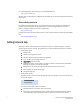
5 Displaying LAG information The Error Details tab shows transmission error statistics (Figure 33). FIGURE 33 FCoE Trunk Error Details tab Displaying LAG information Use the following procedure to display LAG information. 1. Select the CEE tab on the Switch Administration panel. 2. Select the Link Aggregation tab LAG information is displayed (Figure 34). FIGURE 34 LAG information Displaying VLAN information Use the following procedure to display VLAN information. 1.
Displaying FCoE login groups 5 Displaying FCoE login groups Use the following procedure to display FCoE login group information. 1. Select the CEE tab on the Switch Administration panel. 2. Select the FCoE Login tab. FC0E login group information is displayed (Figure 36). FIGURE 36 FCoE login group information Displaying QoS information Use the following procedure to display QoS information. 1. Select the CEE tab on the Switch Administration panel. 2. Select the QoS tab.
5 Displaying DCBX-LLDP information FIGURE 38 Traffic Class Map Information Displaying DCBX-LLDP information Use the following procedure to display DCBX-LLDP information. 1. Select the CEE tab on the Switch Administration panel. 2. Select the DCBX-LLDP tab. - To display global settings, select the Global tab (Figure 39).
Displaying CEE interface statistics FIGURE 40 5 LLDP Profile Information Displaying CEE interface statistics The CEE interface Port Statistics tab shows basic and advanced statistics, and allows you to change statistics collection parameters. Use the following procedure to display CEE interface statistics. 1. Select the CEE Interfaces tab on the Port Administration panel. 2. Under the CEE Interfaces Explorer, select a port. 3. Select the Port Statistics tab.
5 Displaying CEE interface statistics FIGURE 41 CEE Interfaces, Port Statistics, Basic Mode The CEE Trunk Statistics Configuration section allows you to do the following: • Toggle between showing Absolute Values, or Delta Values (values that have changed since the last data collection). • Clear Counters to refresh data. • Change the retrieval interval. To view additional information, select Show Advanced Mode. An Advanced tab and an Error Detail tab are added next to Basic Mode (Figure 42).
Displaying CEE interface statistics FIGURE 42 5 CEE Interface, Port Statistics, Advanced Mode The Advanced tab shows CEE transmission statistics (Figure 43).
5 Displaying CEE interface statistics FIGURE 43 CEE Advanced Performance Statistics The Error Details tab shows transmission error statistics (Figure 44).
Enabling and disabling a CEE interface 5 Enabling and disabling a CEE interface CEE interfaces can be enabled and disabled from a right-click menu on the Switch View, or from the Port Administration panel. To enable or disable a CEE interface from the Switch View, perform the following steps. 1. Right-click the port to display the right-click menu. 2. Select Configure to display the Enable and Disable options. To enable or disable a CEE interface from the Port Administration panel, do the following: 1.
5 Enabling and disabling QoS priority-based flow control 3. Select the General tab. 4. Select Edit Configuration. The CEE Edit Configuration dialog box is displayed. 5. For LLDP Status, select Enable or Disable. Enabling and disabling QoS priority-based flow control Priority-based flow control (PFC) can be used to control network congestion. PFC can be used to selectively pause lower priority traffic classes to ensure that high priority and delay-sensitive traffic are not affected by network congestion.