Troubleshooting Guide HP t620 Flexible Series Thin Client
© Copyright 2013 Hewlett-Packard Development Company, L.P. The information contained herein is subject to change without notice. Microsoft and Windows are U.S. registered trademarks of the Microsoft group of companies. The only warranties for HP products and services are set forth in the express warranty statements accompanying such products and services. Nothing herein should be construed as constituting an additional warranty.
About This Book WARNING! Text set off in this manner indicates that failure to follow directions could result in bodily harm or loss of life. CAUTION: Text set off in this manner indicates that failure to follow directions could result in damage to equipment or loss of information. NOTE: Text set off in this manner provides important supplemental information.
iv About This Book
Table of contents 1 Product features ............................................................................................................... 1 Front panel components ............................................................................................................ 1 Rear panel components ............................................................................................................ 2 Serial number location ......................................................................
Computer Setup—Power .......................................................................................... 38 Computer Setup—Advanced .................................................................................... 38 Changing BIOS Settings from the HP BIOS Configure Utility (HPBCU) ........................................... 40 Appendix B Diagnostics and Troubleshooting ..................................................................... 42 LEDs ...................................................
Index .................................................................................................................................
viii
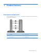
1 Product features Front panel components For more information, go to http://www.hp.com and search for your specific thin client model to find the model-specific QuickSpecs. (1) Power button (4) USB 3.0 ports (2) (2) Flash drive activity LED (5) Microphone port (3) USB 2.
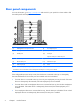
Rear panel components For more information, go to http://www.hp.com and search for your specific thin client model to find the model-specific QuickSpecs. (1) Half-height PCIe 2.0 expansion slot* (8) PS/2 keyboard port (2) Serial port* (9) PS/2 mouse port (3) Parallel port* (10) Serial port Optional: VGA port or fiber NIC port (4) Retractable power cord retention hook (11) Audio line-in port (5) Ethernet RJ-45 port (12) Audio line-out port (6) USB 2.
Presence of an optional VGA or Fiber NIC port does not disable a DisplayPort port. Serial number location Every thin client includes a unique serial number located as shown in the following illustration. Have this number available when contacting HP customer service for assistance.
2 Hardware changes Warnings and cautions Before performing upgrades be sure to carefully read all of the applicable instructions, cautions, and warnings in this guide. WARNING! To reduce the risk of personal injury or equipment damage from electric shock, hot surfaces, or fire: Disconnect the power cord from the power outlet and allow the internal system components to cool before you touch them. Do not plug telecommunications or telephone connectors into the network interface controller (NIC) receptacles.
Connecting the power cord 1. Plug the female end of the power cord into the power supply brick (1). 2. Connect the other end of the power cord to an electrical outlet (2). 3. Connect the round end of the power supply cord to the power supply connector on the rear of the computer (3). 4. Use the slot (4) on the side of the retractable power cord retention hook to pull the hook out. 5. Press the power cord into the retention hook (5) and bundle any excess power cord.
Attaching the stand CAUTION: The computer must be operated with the stand attached to ensure proper airflow around the computer. The computer can be used in either a tower or horizontal orientation with the stand included with the computer. 1. Remove/disengage any security devices that prohibit opening the computer. 2. Remove all removable media, such as USB flash drives, from the computer. 3. Turn off the computer properly through the operating system, and then turn off any external devices. 4.
● 6. Attach the stand to the right side of the computer to use it in the horizontal orientation. a. Lay the computer down with the right side up and locate the two screw holes in the grid on the right side of the computer. b. Position the stand (1) over the side of the computer and line up the captive thumbscrews in the stand with the screw holes in the computer. c. Tighten the captive thumbscrews (2) securely.
Removing and replacing the access panel Removing the access panel WARNING! To reduce the risk of personal injury or equipment damage from electric shock, hot surfaces, or fire, ALWAYS operate the computer with the access panel in place. In addition to enhancing safety, the access panel may provide important instructions and identification information, which may be lost if the access panel is not used. DO NOT use any access panel except the one that is provided by HP for use with this computer.
8. Move the access panel latch (1) to the left to release the access panel. 9. Slide the access panel (2) approximately 6 cm (.24 in) toward the back of the chassis, and then lift the panel off of the computer. Replacing the access panel To replace the access panel: 1. Set the access panel (1) onto the chassis approximately 6 cm (.24 in) inside the edge of the chassis, and then slide the panel toward the front of the chassis until it locks in place. 2.
3. 10 Insert the hooks on the right side of the I/O panel (1) into the right side of the back of the chassis, and then press the left side (2) to the chassis until it locks in place.
Installing internal USB flash drives There are two USB flash drive ports on the system board. To install a USB flash drive: 1. Remove/disengage any security devices that prohibit opening the computer. 2. Remove all removable media, such as USB flash drives, from the computer. 3. Turn off the computer properly through the operating system, and then turn off any external devices. 4. Disconnect the power cord from the power outlet, and disconnect any external devices. 5.
(1) USB-1 port USB 2.0 flash drive: maximum dimensions 55 mm (L) x 16 mm (W) x 8 mm (H) (2) USB-2 port USB 2.0 flash drive: maximum dimensions 65 mm (L) x 25 mm (W) x 10 mm (H) NOTE: Be sure that the USB flash drive to be installed does not exceed the maximum size for that USB port. 9. Align the USB flash drive with the USB port and press the drive firmly into the port until it is securely seated. 10.
11. Replace and latch the access panel, and then reinstall the I/O panel. 12. Replace the computer stand. 13. Reconnect the power cord and turn on the computer. 14. Lock any security devices that were disengaged when the computer cover or access panel was removed. Installing additional memory The computer comes with double data rate 3 synchronous dynamic random access memory (DDR3LSDRAM) small outline dual inline memory modules (SODIMMs).
Populating SODIMM sockets There are two SODIMM sockets on the system board with one total channel. The sockets are labeled DIMM1 and DIMM2. The system operates in single-channel mode at 1600 MHz. Item Description System Board Label Socket Color 1 SODIMM1 socket, Channel A DIMM1 Black 2 SODIMM2 socket, Channel A DIMM2 White NOTE: If both SODIMM sockets are populated with dual-sided SODIMMs, the system memory speed is reduced to 1333 MHz.
Installing SODIMMs CAUTION: You must disconnect the power cord and wait approximately 30 seconds for the power to drain before adding or removing memory modules. Regardless of the power-on state, voltage is always supplied to the memory modules as long as the computer is plugged into an active AC outlet. Adding or removing memory modules while voltage is present may cause irreparable damage to the memory modules or system board. The memory module sockets have gold-plated metal contacts.
16 7. If the computer is an HP t620 PLUS Thin Client, push the fan assembly latch (1) toward the front of the computer and rotate the assembly (2) up and out of the way. 8. Locate the memory compartment on the system board. 9. If a fiber NIC is installed, move the cable carefully out of the slot in the memory compartment cover.
10. Remove the two screws and springs (1) securing the memory compartment cover. NOTE: Be sure to retain the two screws and the springs beneath them. 11. Slide the memory compartment cover (2) slightly toward the front of the computer to free it, and then lift it out of the chassis. 12. To remove a SODIMM, press outward on the two latches (1) on each side of the SODIMM, rotate the SODIMM up (2), and then pull the SODIMM out of the socket (3).
13. Slide the new SODIMM (1) into the socket at approximately a 30° angle, and then press the SODIMM into the socket (2) so that the latches lock it in place. NOTE: A memory module can be installed in only one way. Match the notch on the module with the tab on the memory socket. 14. Hold the memory compartment cover with the fiber NIC slot toward the front of the computer, and then set the memory compartment cover (1) over the SODIMMs. 15.
17. If the computer is an HP t620 PLUS Thin Client, rotate the fan assembly down, push the fan assembly latch (1) toward the front of the computer, lower the assembly (2) until it stops, and then release the latch. 18. Replace and latch the access panel, and then reinstall the I/O panel. 19. Replace the computer stand. 20. Reconnect the power cord and turn on the computer. 21. Lock any security devices that were disengaged when the computer cover or access panel was removed.
Installing a PCI-Express card You may install an optional half-height PCI-Express (PCIe) card in the HP t620 PLUS Thin Client. A riser card is installed in this computer by default. WARNING! To reduce the risk of personal injury or equipment damage from electric shock, hot surfaces, or fire, disconnect the power cord from the power outlet and allow the internal system components to cool before you touch them. To install a PCIe card: 1.
8. Locate the slot in the riser card. 9. Slide the expansion slot cover left and remove it.
10. Align the PCIe card connectors with the slot in the riser card and the metal tab at the end of the card with the slot in the chassis. Press the PCIe card firmly into the slot in the riser card until it is securely seated and the tab is in the slot. 11. Rotate the fan assembly down, push the fan assembly latch (1) toward the front of the computer, lower the assembly (2) until it stops, and then release the latch. 12. Replace and latch the access panel, and then reinstall the I/O panel. 13.
Installing a half-height PCI-Express 2.0 card You may install an optional half-height PCI-Express (PCIe) card in the HP t620 PLUS Thin Client. A riser card is installed in this computer by default. WARNING! To reduce the risk of personal injury or equipment damage from electric shock, hot surfaces, or fire, disconnect the power cord from the power outlet and allow the internal system components to cool before you touch them. To install a PCIe card: 1.
24 8. Locate the slot in the riser card. 9. Slide the expansion slot cover left and remove it.
10. Align the PCIe card connectors with the slot in the riser card and the metal tab at the end of the card with the slot in the chassis. Press the PCIe card firmly into the slot in the riser card until it is securely seated and the tab is in the slot. 11. Rotate the fan assembly down, push the fan assembly latch (1) toward the front of the computer, lower the assembly (2) until it stops, and then release the latch. 12. Replace and latch the access panel, and then reinstall the I/O panel. 13.
Security The thin client is equipped with a hood sensor. You may also use a cable lock to secure the computer. For an additional layer of security, you may purchase a port cover to prevent unauthorized access to the rear ports. Hood sensor The hood sensor is a combination of hardware and software technology. If the access panel is removed, the hood sensor is released and the computer alerts local users to tampering or removal of the access panel.
Cable lock These thin clients are designed to accept a security cable lock. This cable lock prevents unauthorized removal of the thin client, as well as locking devices installed inside the case. To order this option, visit the HP website at http://www.hp.com and search for your specific thin client model. 1. Locate the cable lock slot on the back panel. 2. Insert the cable lock into the slot, and then use the key to lock it.
Removing and replacing the battery WARNING! Before removing the side access panel, be sure that the thin client is turned off and the power cord is disconnected from the electrical outlet. To remove and replace the battery: 1. Remove/disengage any security devices that prohibit opening the computer. 2. Remove all removable media, such as USB flash drives, from the computer. 3. Turn off the computer properly through the operating system, and then turn off any external devices. 4.
c. Pull the riser card out of the socket and carefully move it to one side. Disconnecting the cables from the PCIe riser card is not necessary. 8. Locate the battery on the system board. 9. Carefully pry the battery up from the system board. 10. Unplug the battery cable connector from the system board. 11. Connect the cable connector from the new battery to the system board. 12. Carefully press the new battery down to adhere the battery securely to the system board. 13.
b. Align the riser card with the socket on the system board and press the riser card firm into the socket. NOTE: The riser card can be installed in only one way. Match the notch on the card with the tab on the socket. c. If a PCIe card was installed, reinstall it. For instructions, see Installing a PCI-Express card on page 20. d. Rotate the fan assembly down, push the fan assembly latch (1) toward the front of the computer, lower the assembly (2) until it stops, and then release the latch. 14.
16. Reconnect the power cord and turn on the computer. 17. Lock any security devices that were disengaged when the computer cover or access panel was removed. HP encourages customers to recycle used electronic hardware, HP original print cartridges, and rechargeable batteries. For more information about recycling programs, go to http://www.hp.com and search for “recycle”. Batteries, battery packs, and accumulators should not be disposed of together with the general household waste.
A Computer Setup (F10) Utility, BIOS Settings Computer Setup (F10) Utilities Use Computer Setup (F10) Utility to do the following: 32 ● Change factory default settings. ● Set the system date and time. ● Set, view, change, or verify the system configuration, including settings for processor, graphics, memory, audio, storage, communications, and input devices. ● Modify the boot order of bootable devices such as solid-state drives or USB flash media devices.
Using Computer Setup (F10) Utilities Computer Setup can be accessed only by turning the computer on or restarting the system. To access the Computer Setup Utilities menu, complete the following steps: 1. Turn on or restart the computer. 2. Press either Esc or F10 while the “Press the ESC key for Startup Menu” message is displayed at the bottom of the screen. Pressing Esc displays a menu that allows you to access different options available at startup.
Computer Setup—File NOTE: Support for specific Computer Setup options may vary depending on the hardware configuration.
Computer Setup—Storage Option Description Device Configuration Lists all installed BIOS-controlled storage devices. When a device is selected, detailed information and options are displayed. The following options may be presented: Hard Disk: Size, model, firmware version, serial number. Storage Options SATA Emulation CAUTION: SATA emulation changes may prevent access to existing drive data and degrade or corrupt established volumes.
Computer Setup—Security NOTE: Support for specific Computer Setup options may vary depending on the hardware configuration. Table A-1 Computer Setup—Security Option Description Setup Password Allows you to set and enable a setup (administrator) password. NOTE: If the setup password is set, it is required to change Computer Setup options, flash the ROM, and make changes to certain plug and play settings under Windows. Power-On Password Allows you to set and enable a power-on password.
Table A-1 Computer Setup—Security (continued) Slot Security Allows you to disable the PCI Express slot and Mini Card Slot. Default is enabled. ● PCI Express x4 Slot # ● Mini Card Slot Network Boot Enables/disables the computer’s ability to boot from an operating system installed on a network server. (Feature available on NIC models only; the network controller must be either a PCI expansion card or embedded on the system board.) Default is enabled.
Computer Setup—Power NOTE: Support for specific Computer Setup options may vary depending on the hardware configuration. Table A-2 Computer Setup—Power Option Description Hardware Power Management SATA Power Management – Enables or disables SATA bus and/or device power management. Default is enabled. S5 Maximum Power Savings – Turns off power to all nonessential hardware when system is off to meet EUP Lot 6 requirement of less than 0.5 Watt power usage. Default is disabled.
Table A-3 Computer Setup—Advanced (for advanced users) (continued) Bus Options Device Options On some models, allows you to enable or disable: ● PCI SERR# Generation. Default is enabled. ● PCI VGA Palette Snooping, which sets the VGA palette snooping bit in PCI configuration space; only needed when more than one graphics controller is installed. Default is disabled. Allows you to set: ● Printer mode (Bi-Directional, EPP + ECP, Output Only). Default is EPP+ECP. ● Num Lock State at Power-On (off/on).
Changing BIOS Settings from the HP BIOS Configure Utility (HPBCU) Some BIOS settings may be changed locally within the operating system without having to go through the F10 utility1. This table identifies the items that can be controlled with this method.
Smart Cover Disable Notify, User SATA Power Management Enable Disable S5 Maximum Power Savings Disable Enable S4/S5 Wake on LAN Disable Enable CPU Fan Check Enable Disable POST Messages Disable Enable After Power Loss Off On, Previous State POST Delay (in seconds) None 5, 10, 15, 20, 60 Power on Sunday – Saturday Disable Enable Power on Time (hh:mm) 00:00 00:00:23:59 Serial Port A IO=3F8; IRQ=4 Disable, IO=3F8h; IRQ=3, IO=2F8h; IRQ=4, IO=2F8h; IRQ=3, IO=3E8h; IRQ=4, IO=3E8h;
B Diagnostics and Troubleshooting LEDs Table B-1 Power and IDE Flash Activity LEDs LED Status Power LED Off When the unit is plugged into the wall socket and the Power LED is off, the unit is powered off. However, the network can trigger a Wake On LAN event in order to perform management functions. Power LED On Displays during boot sequence and while the unit is on.
Wake-on LAN Wake-on LAN (WOL) allows a computer to be turned on or resumed from sleep or hibernation state by a network message. You can enable or disable WOL in Computer Setup using the S5 Maximum Power Savings setting. To enable or disable WOL: 1. Turn on or restart the computer. 2. Press either Esc or F10 while the “Press the ESC key for Startup Menu” message is displayed at the bottom of the screen.
Resetting the Setup and power-on Passwords You can reset the Setup and Power-on passwords as follows: 1. Turn off the computer and disconnect the power cord from the power outlet. 2. Remove the side access panel and the metal side cover. 3. Remove the password jumper from the system board header labeled PSWD/E49. 4. Replace the metal side cover and the side access panel. 5. Connect the computer to AC power, and then turn on the computer. 6.
Interpreting POST Diagnostic Front Panel LEDs and Audible Codes This section covers the front panel LED codes as well as the audible codes that may occur before or during POST that do not necessarily have an error code or text message associated with them. WARNING! When the computer is plugged into an AC power source, voltage is always applied to the system board.
Table B-3 Diagnostic Front Panel LEDs and Audible Codes (continued) Activity Beeps Possible Cause Recommended Action Red Power LED flashes four times, once every second, followed by a two second pause. Beeps stop after fifth iteration but LEDs continue until problem is solved. 4 Power failure (power supply is overloaded). 1. Check if a device is causing the problem by removing ALL attached devices. Power on the system.
Table B-3 Diagnostic Front Panel LEDs and Audible Codes (continued) Activity Beeps Possible Cause Recommended Action Red Power LED flashes eight times, once every second, followed by a two second pause. Beeps stop after fifth iteration but LEDs continue until problem is solved. 8 Invalid ROM based on bad checksum. 1. Reflash the system ROM with the latest BIOS image using the BIOS Recovery procedure. 2. Replace the system board. System does not power on and LEDs are not flashing.
POST Numeric Codes and Text Messages This section covers those POST errors that have numeric codes associated with them. The section also includes some text messages that may be encountered during POST. NOTE: The computer will beep once after a POST text message is displayed on the screen. Table B-4 Numeric Codes and Text Messages Control panel message Description Recommended action 103-System Board Failure DMA or timers. 1. Clear CMOS. 2. Remove expansion boards. 3. Replace the system board. 1.
Table B-4 Numeric Codes and Text Messages (continued) Control panel message Description Recommended action 301-Keyboard Error Keyboard failure. 1. Reconnect keyboard with computer turned off. 2. Check connector for bent or missing pins. 3. Ensure that none of the keys are depressed. 4. Replace keyboard. 510-Flash Screen Image Corrupted Flash Screen image has errors. Reflash the system ROM with the latest BIOS image.
Table B-4 Numeric Codes and Text Messages (continued) Control panel message Description Recommended action Network Server Mode Active and No Keyboard Attached Keyboard failure while Network Server Mode enabled. 1. Reconnect keyboard with computer turned off. 2. Check connector for bent or missing pins. 3. Ensure that none of the keys are depressed. 4. Replace keyboard. Parity Check 2 Parity RAM failure. Run Computer Setup and Diagnostic utilities.
Table B-5 Power-On Troubleshooting (continued) No link or activity on the network RJ-45 LEDs or the LEDs do not illuminate blinking green after powering on the thin client unit. (The network LEDs are located inside the RJ-45 connector on the top, rear panel of the thin client. Indicator lights are visible when the connector is installed.) 1. Verify that the network is not down. 2.
Diskless (No-Flash) Unit Troubleshooting This section is only for those units that do not have ATA Flash capability. Because there is no ATA Flash in this model the boot priority sequence is: ● USB device ● PXE 1. When the unit boots, the monitor should display the following information: Table B-6 Diskless Unit Troubleshooting Item Information Action MAC Address NIC portion of the system board is OK If no MAC Address, the system board is at fault. Contact the Call Center for service.
Configuring a PXE Server NOTE: All PXE software is supported by authorized service providers on a warranty or service contract basis. Customers that call the HP Customer Service Center with PXE issues and questions should be referred to their PXE provider for assistance. Additionally, refer to the following: – For Windows 2008 R2: http://support.microsoft.com/kb/891275 – For Windows 2012: http://technet.microsoft.com/en-us/library/cc766320(WS.10).
C Restoring the Flash Image System Requirements To create a recovery device for the purpose of reflashing or restoring the software image on the ROM, you will need the following: ● A personal computer running Microsoft Windows XP Professional or Windows 7. ● One or more HP t620 Flexible Thin Clients ● 8-GB USB flash device for Microsoft Windows Embedded Standard 7 (WES 7) (if using the USB format) or Linux. This restore method will not work with all USB flash devices.
first restart of the thin client following the restore process, it may take approximately 15 minutes to unbundle the software before the Windows Desktop is displayed. Formatting a USB Flash Drive CAUTION: To prevent loss of data, be sure that you have saved any user-created data from the USB drive to another drive. 1. Connect your USB flash device (drive key) to your personal computer. Ensure that only one USB flash device is connected to the system. 2. Click USB Format. 3.
Deploying with PXE 1. Ensure that IBRPE.EXE and FLASH.IBR file exist. 2. Add the following command to execute IBRPE in WinPE environment: [full path] \IBRPE.EXE [full path]\FLASH.IBR HD0 To view the IBR command line options: At the command prompt, type IBR.EXE /? and press Enter. See your documentation if using a different PXE server, such as Altiris Deployment Solution.
D Device management The t620 includes a license for HP Device Manager and has a Device Manager agent pre-installed. HP Device Manager is a thin client optimized management tool used to manage the full life cycle of HP thin clients to include Discover, Asset Management, Deployment and Configuration. For more information on HP Device Manager, please visit www.hp.com/go/hpdm. If you wish to manage the t620 with other management tools such as Microsoft SCCM or LANDesk, go to www.hp.
E Adding an Image Restore Tool 1. Ensure that the boot order is set to use the Network as the first boot device. 2. Ensure that IBR.exe (Image Restore) and Flash.dd are stored in the same directory on the server. (e.g., c:\program files\altiris\express\deployment server\images) 3. From the Altiris Deployment Server Console, click File > New > Job . 4. Enter a unique name for the job that you will use to deploy the original thin client image. 5. Click the name of the new job. 6.
F System BIOS Updating or restoring a BIOS HP Device Manager HP Device Manager can be used to update the BIOS of a thin client. Customers can use a pre-built BIOS add-on or can use the standard BIOS upgrade package along with an HP Device Manager File and Registry template. For more information on HP Device Manager File and Registry templates, review the HP Device Manager User Guide found at www.hp.com/go/hpdm.
As a general rule, updating the BIOS will modify measurement values stored in the Platform Configuration Registers (PCRs) of the system's security module. Temporarily disable technologies that use these PCR values to ascertain platform health (BDE is one such example) prior to flashing the BIOS. Once you update the BIOS, re-enable the functions and restart the system so that you can take new measurements.
G Power cord set requirements The power supplies on some computers have external power switches. The voltage select switch feature on the computer permits it to operate from any line voltage between 100-120 or 220-240 volts AC. Power supplies on those computers that do not have external power switches are equipped with internal switches that sense the incoming voltage and automatically switch to the proper voltage.
Country-specific requirements Additional requirements specific to a country are shown in parentheses and explained below. 62 Country Accrediting Agency Country Accrediting Agency Australia (1) EANSW Italy (1) IMQ Austria (1) OVE Japan (3) METI Belgium (1) CEBC Norway (1) NEMKO Canada (2) CSA Sweden (1) SEMKO Denmark (1) DEMKO Switzerland (1) SEV Finland (1) SETI United Kingdom (1) BSI France (1) UTE United States (2) UL Germany (1) VDE 1.
H Statement of Volatility Thin Client products typically have three types of memory devices namely, RAM, ROM, and Flash memory devices. Data stored in the RAM memory device will be lost once the power is removed from the device. RAM devices could be powered by main, aux, or battery power (power states are explained below). Therefore, even when the unit is not connected to an AC outlet, some of the RAM devices could be powered by battery power.
Model Description Location/Size Power Loss of data Comments System Boot ROM (BIOS) SPI ROM (64 Mbit) socketed, removable. System memory (RAM) SODIMM socket. Removable (4GB/ 8GB) Main power If main power is removed Only S0/S3/S5/ G3 ACPI states are supported RTC (CMOS) RAM RTC RAM is 256 bytes RAM Memory embedded in AMD APU’s System on Chip (SOC). Main/battery If battery power is removed Keyboard/mouse (ROM) RTC RAM is 256 bytes RAM Memory embedded in AMD APU’s System on Chip (SOC).
I Specifications Dimensions Width: HP t620 Thin Client 40 mm 1.57 in. Width: HP t620 PLUS Thin Client 65 mm 2.56 in. Depth 240 mm 9.45 in Height (without stand) 219.70 mm 8.65 In Height (with stand) 220 mm 8.66 in. Operating** 10°C to 40°C 50°F to 104°F With the fiber NIC is installed 10°C to 35°C 50°F to 95°F -30°C to 60°C -22°F to 140°F Temperature Range (fanless design)* (max. rate of change is 10°C per hour or 18°F per hour) Nonoperating (max.
Maximum Altitude (unpressurized) 3048 m 10,000 ft 9144 m 30,000 ft Power Supply HP t620 Thin Client HP t620 PLUS Thin Client Operating Voltage Range 100 VAC to 240 VAC 100 VAC to 240 VAC Rated Line Frequency 50 Hz to 60 Hz 50 Hz to 60 Hz Power Output (maximum) 65 W 85 W Rated Output Current (maximum) 3.33 A 4.36 A Output Voltage +19.5 V dc +19.5 V dc Operating (max. allowed rate of change is 457m per minute or 1500 ft per minute) Nonoperating (max.
Index A access panel removing 8 replacing 9 adding an image restore tool 58 altitude specifications 66 audible codes 45 B basic troubleshooting 50 battery, replacing 28 beep codes 45 BIOS 59 updating 59 C cable lock 27 cable routing slot 2 cautions attaching the stand 6 electric shock 4, 8, 15, 20, 23 installing SODIMMs 15 removing the battery 28 securing the power cable 5 static electricity 4 changing BIOS settings in the REPSETUP utility 40 components front panel 1 rear panel 2 country power cord set req
removing access panel 8 battery 28 replacing access panel 9 battery 28 resetting the Administrator password 44 restore 58 restoring the flash image 54 RJ-45 connector location 2 S secure cable routing slot 2 security 26 cable lock 27 hood sensor 26 serial connector location 2 serial number location 3 specifications altitude 66 computer 65 dimensions 65 humidity 65 power output 66 power supply 66 rated output current 66 relative humidity 65 temperature 65 specifications, memory 13 stand, attaching 6 T temper