Hardware Reference Guide HP t620 Flexible Series Thin Client
© Copyright 2013 Hewlett-Packard Development Company, L.P. The information contained herein is subject to change without notice. Microsoft and Windows are U.S. registered trademarks of Microsoft Corporation. The only warranties for HP products and services are set forth in the express warranty statements accompanying such products and services. Nothing herein should be construed as constituting an additional warranty. HP shall not be liable for technical or editorial errors or omissions contained herein.
About This Book WARNING! Text set off in this manner indicates that failure to follow directions could result in bodily harm or loss of life. CAUTION: Text set off in this manner indicates that failure to follow directions could result in damage to equipment or loss of information. NOTE: Text set off in this manner provides important supplemental information.
iv About This Book
Table of contents 1 Product features ............................................................................................................................................. 1 Standard features ................................................................................................................................. 1 Front panel components ....................................................................................................................... 2 Rear panel components .............
Appendix B Removing and replacing the battery ......................................................................................... 34 Appendix C Thin client operation ................................................................................................................... 38 Routine thin client care ....................................................................................................................... 38 Supported orientations ..................................................
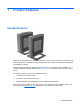
1 Product features Standard features Thank you for purchasing an HP thin client. We hope you have years of use from our thin clients. Our goal is to provide you with award-winning clients that are easy to deploy and manage with the power and reliability you expect. The next sections describe the features of the thin client. For a complete list of the hardware and software installed on a specific model, visit http://www.hp.com and search for your specific thin client model.
CAUTION: Ensure that the write filter is enabled after committing necessary configurations to the thin client flash drive. During normal operation of the thin client, the write filter must be enabled. Also ensure that Page File is not enabled on thin clients with flash memory storage. Failure to follow these required actions can void the warranty of the flash storage device.
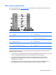
Rear panel components For more information, go to http://www.hp.com and search for your specific thin client model to find the model-specific QuickSpecs. (1) Half-height PCIe 2.0 expansion slot* (8) PS/2 keyboard port (2) Serial port* (9) PS/2 mouse port (3) Parallel port* (10) Serial port Optional: VGA port or fiber NIC port (4) Retractable power cord retention hook (11) Audio line-in port (5) Ethernet RJ-45 port (12) Audio line-out port (6) USB 2.
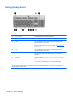
Using the keyboard (1) Caps Lock key Activates/deactivates the Caps Lock feature. (2) Scroll Lock key Activates/deactivates the Scroll Lock feature. (3) Num Lock key Activates/deactivates the Num Lock feature. (4) Ctrl key Use in combination with another key; its function depends on the application software you are using. (5) Windows Logo Key1, 2 Opens the Start menu in Windows®. Use in combination with other keys to perform other functions.
Windows Logo Key Use the Windows Logo Key in combination with other keys to perform certain functions available in Windows operating systems. Windows Logo Key + Tab Switch between open items. Windows Logo Key + e Open My Computer. Windows Logo Key + f Search for a file or folder. Windows Logo Key + Ctrl + f Search for computers. Windows Logo Key + m Minimize all windows. Windows Logo Key + Shift + m Undo minimize all. Windows Logo Key + Break Display the System Properties dialog box.
Serial number location Every thin client includes a unique serial number located as shown in the following illustration. Have this number available when contacting HP customer service for assistance.
2 Hardware changes Warnings and cautions Before performing upgrades be sure to carefully read all of the applicable instructions, cautions, and warnings in this guide. WARNING! To reduce the risk of personal injury or equipment damage from electric shock, hot surfaces, or fire: Disconnect the power cord from the power outlet and allow the internal system components to cool before you touch them. Do not plug telecommunications or telephone connectors into the network interface controller (NIC) receptacles.
Connecting the power cord 1. Plug the female end of the power cord into the power supply brick (1). 2. Connect the other end of the power cord to an electrical outlet (2). 3. Connect the round end of the power supply cord to the power supply connector on the rear of the computer (3). 4. Use the slot (4) on the side of the retractable power cord retention hook to pull the hook out. 5. Press the power cord into the retention hook (5) and bundle any excess power cord.
Attaching the stand CAUTION: The computer must be operated with the stand attached to ensure proper airflow around the computer. The computer can be used in either a tower or horizontal orientation with the stand included with the computer. 1. Remove/disengage any security devices that prohibit opening the computer. 2. Remove all removable media, such as USB flash drives, from the computer. 3. Turn off the computer properly through the operating system, and then turn off any external devices. 4.
6. Reconnect the external equipment, plug the power cord into a power outlet, and then turn the computer on. NOTE: Be sure that at least 10.2 centimeters (4 inches) of space on all sides of the computer remain clear and free of obstructions. NOTE: An optional Quick Release mounting bracket is available from HP for mounting the computer to a wall, desk, or swing arm. When the mounting bracket is used, do not install the computer with the I/O ports oriented towards the ground.
4. Disconnect the power cord from the power outlet, and disconnect any external devices. CAUTION: Regardless of the power-on state, voltage is always present on the system board as long as the system is plugged into an active AC outlet. You must disconnect the power cord to avoid damage to the internal components of the computer. 5. Remove the computer from the stand. 6. Lay the unit flat on a stable surface with the right side up. 7.
Replacing the access panel To replace the access panel: 12 1. Position the access panel (1) on the chassis, approximately 6 mm (.24 in) inside the edge of the chassis. Be sure that the access panel covers the hood sensor, and then slide the panel toward the front of the chassis (2) until it locks into place. 2. Move the access panel latch (3) to the right to secure the access panel.
3. Insert the hooks on the right side of the I/O panel (1) into the right side of the back of the chassis, and then press the left side (2) to the chassis until it locks in place.
Installing internal USB flash drives There are two USB flash drive ports on the system board. To install a USB flash drive: 1. Remove/disengage any security devices that prohibit opening the computer. 2. Remove all removable media, such as USB flash drives, from the computer. 3. Turn off the computer properly through the operating system, and then turn off any external devices. 4. Disconnect the power cord from the power outlet, and disconnect any external devices. 5.
(1) USB-1 port USB 2.0 flash drive: maximum dimensions 55 mm (L) x 16 mm (W) x 8 mm (H) (2) USB-2 port USB 2.0 flash drive: maximum dimensions 65 mm (L) x 25 mm (W) x 10 mm (H) NOTE: Be sure that the USB flash drive to be installed does not exceed the maximum size for that USB port. 9. Align the USB flash drive with the USB port and press the drive firmly into the port until it is securely seated. 10.
12. Replace the computer stand. 13. Reconnect the power cord and turn on the computer. 14. Lock any security devices that were disengaged when the computer cover or access panel was removed. Installing additional memory The computer comes with double data rate 3 synchronous dynamic random access memory (DDR3LSDRAM) small outline dual inline memory modules (SODIMMs). SODIMMs The memory sockets on the system board can be populated with up to two industry-standard SODIMMs.
Populating SODIMM sockets There are two SODIMM sockets on the system board. The sockets are labeled DIMM1 and DIMM2. Item Description System Board Label Socket Color 1 SODIMM1 socket DIMM1 Black 2 SODIMM2 socket DIMM2 White The system operates in single-channel mode. NOTE: If both SODIMM sockets are populated with dual-sided SODIMMs, the system memory speed is reduced to 1333 MHz.
3. Turn off the computer properly through the operating system, and then turn off any external devices. 4. Disconnect the power cord from the power outlet, and disconnect any external devices. CAUTION: You must disconnect the power cord and wait approximately 30 seconds for the power to drain before adding or removing memory modules. Regardless of the power-on state, voltage is always supplied to the memory modules as long as the computer is plugged into an active AC outlet.
8. Locate the memory compartment on the system board. 9. If a fiber NIC is installed, move the cable carefully out of the slot in the memory compartment cover. 10. Remove the two screws and springs (1) securing the memory compartment cover. NOTE: Be sure to retain the two screws and the springs beneath them. 11. Slide the memory compartment cover (2) slightly toward the front of the computer to free it, and then lift it out of the chassis.
12. To remove a SODIMM, press outward on the two latches (1) on each side of the SODIMM, rotate the SODIMM up (2), and then pull the SODIMM out of the socket (3). 13. Slide the new SODIMM (1) into the socket at approximately a 30° angle, and then press the SODIMM into the socket (2) so that the latches lock it in place. NOTE: A memory module can be installed in only one way. Match the notch on the module with the tab on the memory socket.
14. Hold the memory compartment cover with the fiber NIC slot toward the front of the computer, and then set the memory compartment cover (1) over the SODIMMs. 15. If a fiber NIC is installed, move the cable carefully into the slot in the memory compartment cover. 16. Line up the screw holes in the memory cover with the screw posts in the chassis, and then fasten the two screws (2) with the springs to secure the memory compartment cover. 17.
20. Reconnect the power cord and turn on the computer. 21. Lock any security devices that were disengaged when the computer cover or access panel was removed. The computer automatically recognizes the additional memory when you turn on the computer.
Installing a half-height PCI-Express 2.0 card You may install an optional half-height PCI-Express (PCIe) card in the HP t620 PLUS Thin Client. A riser card is installed in this computer by default. WARNING! To reduce the risk of personal injury or equipment damage from electric shock, hot surfaces, or fire, disconnect the power cord from the power outlet and allow the internal system components to cool before you touch them. To install a PCIe card: 1.
24 8. Locate the slot in the riser card. 9. Slide the expansion slot cover left and remove it.
10. Align the PCIe card connectors with the slot in the riser card and the metal tab at the end of the card with the slot in the chassis. Press the PCIe card firmly into the slot in the riser card until it is securely seated and the tab is in the slot. 11. Rotate the fan assembly down, push the fan assembly latch (1) toward the front of the computer, lower the assembly (2) until it stops, and then release the latch. 12. Replace and latch the access panel, and then reinstall the I/O panel. 13.
Security The thin client is equipped with a hood sensor. You may also use a cable lock to secure the computer. For an additional layer of security, you may purchase a port cover to prevent unauthorized access to the rear ports. Hood sensor The hood sensor is a combination of hardware and software technology. If the access panel is removed, the hood sensor is released and the computer alerts local users to tampering or removal of the access panel.
Cable lock These thin clients are designed to accept a security cable lock. This cable lock prevents unauthorized removal of the thin client, as well as locking devices installed inside the case. To order this option, visit the HP website at http://www.hp.com and search for your specific thin client model. 1. Locate the cable lock slot on the back panel. 2. Insert the cable lock into the slot, and then use the key to lock it.
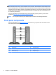
Mounting the thin client HP t620 Thin Client: HP recommends mounting the thin client in the vertical (tower) orientation, with the HP logo right-side up. Mounting in other orientations may result in decreased performance under certain conditions; operating the computer with limited power to prevent overheating is one such condition.
2. Using four 15 mm screws included in the mounting device kit, attach one side of the HP Quick Release to the thin client as shown in the following illustration. 3. Using four screws included in the mounting device kit, attach the other side of the HP Quick Release to the device to which you will mount the thin client. Make sure the release lever points upward.
4. Slide the side of the mounting device attached to the thin client (1) over the other side of the mounting device (2) on the device on which you want to mount the thin client. An audible 'click' indicates a secure connection. When attached, the HP Quick Release automatically locks in position. You only need to slide the lever to one side to remove the thin client.
Supported mounting options The following illustrations demonstrate some of the supported mounting options for the mounting bracket.
A Specifications For the latest specifications or additional specifications on the HP t620 Thin Client or the HP t620 PLUS Thin Client, go to http://www.hp.com/go/ quickspecs/ and search for your specific model to find the model-specific QuickSpecs. Dimensions Width: HP t620 Thin Client 40 mm 1.57 in. Width: HP t620 PLUS Thin Client 65 mm 2.56 in. Depth 240 mm 9.45 in Height (without stand) 219.70 mm 8.65 In Height (with stand) 220 mm 8.66 in.
Maximum Altitude (unpressurized) 3048 m 10,000 ft 9144 m 30,000 ft Power Supply HP t620 Thin Client HP t620 PLUS Thin Client Operating Voltage Range 100 VAC to 240 VAC 100 VAC to 240 VAC Rated Line Frequency 50 Hz to 60 Hz 50 Hz to 60 Hz Power Output (maximum) 65 W 85 W Rated Output Current (maximum) 3.33 A 4.36 A Output Voltage +19.5 V dc +19.5 V dc Operating (max. allowed rate of change is 457m per minute or 1500 ft per minute) Nonoperating (max.
B Removing and replacing the battery WARNING! Before removing the side access panel, be sure that the thin client is turned off and the power cord is disconnected from the electrical outlet. To remove and replace the battery: 1. Remove/disengage any security devices that prohibit opening the computer. 2. Remove all removable media, such as USB flash drives, from the computer. 3. Turn off the computer properly through the operating system, and then turn off any external devices. 4.
7. If the computer is an HP t620 PLUS Thin Client, perform the following steps: a. Push the fan assembly latch (1) toward the front of the computer and rotate the assembly (2) up and out of the way. b. If a PCIe card is installed, remove it carefully. c. Pull the riser card out of the socket and carefully move it to one side. Disconnecting the cables from the PCIe riser card is not necessary.
8. Locate the battery on the system board. 9. Carefully pry the battery up from the system board. 10. Unplug the battery cable connector from the system board. 11. Connect the cable connector from the new battery to the system board. 12. Carefully press the new battery down to adhere the battery securely to the system board. 13. If the computer is an HP t620 PLUS Thin Client, perform the following steps. a. If the cables from the PCIe riser card were disconnected in step 7 c, reconnect them. b.
c. If a PCIe card was installed, reinstall it. For instructions, see Installing a half-height PCIExpress 2.0 card on page 23. d. Rotate the fan assembly down, push the fan assembly latch (1) toward the front of the computer, lower the assembly (2) until it stops, and then release the latch. 14. Replace and latch the access panel, and then reinstall the I/O panel. 15. Replace the computer stand. 16. Reconnect the power cord and turn on the computer. 17.
C Thin client operation CAUTION: Ensure that the write filter is enabled after committing necessary configurations to the thin client flash drive. During normal operation of the thin client, the write filter must be enabled. Also ensure that Page File is not enabled on thin clients with flash memory storage. Failure to follow these required actions can void the warranty of the flash storage device.
Supported orientations HP supports the following orientations for the thin client. CAUTION: You must adhere to HP-supported orientations to be sure that your thin client functions properly. NOTE: HP t620 standard (slim) chassis: HP recommends mounting the thin client in the vertical (tower) orientation, with the HP logo right-side up.
40 Appendix C Thin client operation
Non-supported orientation HP does not support the following orientations for the thin client. CAUTION: Non-supported placement of thin clients could result in operation failure and/or damage to the devices. CAUTION: Thin clients require proper ventilation to maintain operating temperature. Do not block the vents. Do not put thin clients in drawers or other sealed enclosures. Do not place a monitor or other object on top of the thin client.
D Electrostatic discharge A discharge of static electricity from a finger or other conductor may damage system boards or other static-sensitive devices. This type of damage may reduce the life expectancy of the device. Preventing electrostatic damage To prevent electrostatic damage, observe the following precautions: ● Avoid hand contact by transporting and storing products in static-safe containers.
E Shipping information Shipping preparation Follow these suggestions when preparing to ship the thin client: 1. Turn off the thin client and external devices. 2. Disconnect the power cord from the electrical outlet, and then from the thin client. 3. Disconnect the system components and external devices from their power sources, and then from the thin client. 4.
4. Disconnect the power cord from the power outlet, and disconnect any external devices. CAUTION: Regardless of the power-on state, voltage is always present on the system board as long as the system is plugged into an active AC outlet. You must disconnect the power cord to avoid damage to the internal components of the computer. 44 5. Remove the computer from the stand and lay the computer down with the right side up. 6. Remove the computer access panel and back I/O panel.
9. Carefully pull the SSD out of the socket. Store the SSD carefully until it can be installed in the returned computer. 10. Rotate the fan assembly down, push the fan assembly latch (1) toward the front of the computer, lower the assembly (2) until it stops, and then release the latch. 11. Replace and latch the access panel, and then reinstall the I/O panel.
Index A access panel removing 10 replacing 12 altitude specifications 33 F fiber NIC port location 3 Flash drive activity LED location 2 flash memory, removing 43 front panel components 2 function keys 5 B battery, replacing 34 C cable lock 27 cable lock slot 3 cautions attaching the stand 9 damage to flash storage device 2, 38 electric shock 7, 10, 17, 23 HP Quick Release 30 installing SODIMMs 17 removing the battery 34 securing the power cable 8 static electricity 7 thin client orientation 39, 41 venti
rear panel components 3 recycling 37 relative humidity specifications 32 removing access panel 10 battery 34 flash memory 43 solid state drive 43 SSD 43 replacing access panel 12 battery 34 retention hook location 3 RJ-45 connector location 3 routine care 38 S security 26 cable lock 27 hood sensor 26 serial number location 6 serial port location 3 service repair 43 shipping preparation 43 SODIMMs installation 16 socket population 17 solid state drive, removing 43 specifications altitude 33 dimensions 32 har