HP StorageWorks 600 Modular Disk System Maintenance and Service Guide Part Number 495106-001 September 2008 (First Edition)
© Copyright 2008 Hewlett-Packard Development Company, L.P. The information contained herein is subject to change without notice. The only warranties for HP products and services are set forth in the express warranty statements accompanying such products and services. Nothing herein should be construed as constituting an additional warranty. HP shall not be liable for technical or editorial errors or omissions contained herein. Microsoft and Windows are U.S. registered trademarks of Microsoft Corporation.
Contents Customer self repair ...................................................................................................................... 5 Parts only warranty service ......................................................................................................................... 5 Illustrated parts catalog ............................................................................................................... 16 Mechanical components.............................................
Index.........................................................................................................................................
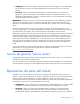
Customer self repair HP products are designed with many Customer Self Repair (CSR) parts to minimize repair time and allow for greater flexibility in performing defective parts replacement. If during the diagnosis period HP (or HP service providers or service partners) identifies that the repair can be accomplished by the use of a CSR part, HP will ship that part directly to you for replacement. There are two categories of CSR parts: • Mandatory—Parts for which customer self repair is mandatory.
• Obligatoire - Pièces pour lesquelles la réparation par le client est obligatoire. Si vous demandez à HP de remplacer ces pièces, les coûts de déplacement et main d'œuvre du service vous seront facturés. • Facultatif - Pièces pour lesquelles la réparation par le client est facultative. Ces pièces sont également conçues pour permettre au client d'effectuer lui-même la réparation.
NOTA: alcuni componenti HP non sono progettati per la riparazione da parte del cliente. Per rispettare la garanzia, HP richiede che queste parti siano sostituite da un centro di assistenza autorizzato. Tali parti sono identificate da un "No" nel Catalogo illustrato dei componenti. In base alla disponibilità e alla località geografica, le parti CSR vengono spedite con consegna entro il giorno lavorativo seguente.
anrufen und sich von einem Mitarbeiter per Telefon helfen lassen. Den Materialien, die mit einem CSRErsatzteil geliefert werden, können Sie entnehmen, ob das defekte Teil an HP zurückgeschickt werden muss. Wenn es erforderlich ist, das defekte Teil an HP zurückzuschicken, müssen Sie dies innerhalb eines vorgegebenen Zeitraums tun, in der Regel innerhalb von fünf (5) Geschäftstagen.
Centro de asistencia técnica de HP y recibirá ayuda telefónica por parte de un técnico. Con el envío de materiales para la sustitución de componentes CSR, HP especificará si los componentes defectuosos deberán devolverse a HP. En aquellos casos en los que sea necesario devolver algún componente a HP, deberá hacerlo en el periodo de tiempo especificado, normalmente cinco días laborables. Los componentes defectuosos deberán devolverse con toda la documentación relacionada y con el embalaje de envío.
periode, gewoonlijk vijf (5) werkdagen, retourneren aan HP. Het defecte onderdeel moet met de bijbehorende documentatie worden geretourneerd in het meegeleverde verpakkingsmateriaal. Als u het defecte onderdeel niet terugzendt, kan HP u voor het vervangende onderdeel kosten in rekening brengen. Bij reparatie door de klant betaalt HP alle verzendkosten voor het vervangende en geretourneerde onderdeel en kiest HP zelf welke koerier/transportonderneming hiervoor wordt gebruikt.
Serviço de garantia apenas para peças A garantia limitada da HP pode incluir um serviço de garantia apenas para peças. Segundo os termos do serviço de garantia apenas para peças, a HP fornece as peças de reposição sem cobrar nenhuma taxa. No caso desse serviço, a substituição de peças CSR é obrigatória. Se desejar que a HP substitua essas peças, serão cobradas as despesas de transporte e mão-de-obra do serviço.
Customer self repair 12
Customer self repair 13
Customer self repair 14
Customer self repair 15
Illustrated parts catalog Mechanical components Item Description Spare part number Customer self repair (on page 5) 1 Chassis — — 2 Internal rail kit 455980-001 No3 3 Hard drive drawer bezel 455973-001 Optional2 Mandatory—Parts for which customer self repair is mandatory. If you request HP to replace these parts, you will be charged for the travel and labor costs of this service. 2 Optional—Parts for which customer self repair is optional.
Optional: Opzionali—Parti la cui riparazione da parte del cliente è facoltativa. Si tratta comunque di componenti progettati per questo scopo. Se tuttavia il cliente ne richiede la sostituzione ad HP, potrebbe dover sostenere spese addizionali a seconda del tipo di garanzia previsto per il prodotto. 3 No: Non CSR—Alcuni componenti HP non sono progettati per la riparazione da parte del cliente. Per rispettare la garanzia, HP richiede che queste parti siano sostituite da un centro di assistenza autorizzato.
Illustrated parts catalog 18
System components Item Description Spare part number Customer self repair (on page 5) 4 I/O module with tray and cable 498472-001 Mandatory1 5 Fan 413996-001 Mandatory1 6 Power supply 441830-001 Mandatory1 7 Power block board kit 455975-001 Optional2 a) UID/power switch board with cables — — b) Dual 7-segment display board with cables — — Power block with power backplane boards 455974-001 Optional2 8 Illustrated parts catalog 19
Item Description Spare part number Customer self repair (on page 5) 9 Fan power board with cables 455977-001 No3 10 Hard drive drawer with hard drive backplane and cables 455976-001 No3 11 Extension arm with cables 455978-001 No3 12 LED display board with cable 455979-001 Optional2 13 Rackmount kit* 432461-001 Mandatory1 14 Hard drive blank* 389015-001 Mandatory1 * Not shown 1 Mandatory—Parts for which customer self repair is mandatory.
HP realice su sustitución, puede o no conllevar costes adicionales, dependiendo del tipo de servicio de garantía correspondiente al producto. 3 No: No—Algunos componentes no están diseñados para que puedan ser reparados por el usuario. Para que el usuario haga valer su garantía, HP pone como condición que un proveedor de servicios autorizado realice la sustitución de estos componentes. Dichos componentes se identifican con la palabra “No” en el catálogo ilustrado de componentes.
Removal and replacement procedures Required tools The following items are required for some procedures: • T-8 Torx screwdriver • T-10 Torx screwdriver • T-15 Torx screwdriver • Phillips screwdriver Safety considerations Before performing service procedures, review all the safety information. Preventing electrostatic discharge To prevent damaging the system, be aware of the precautions you need to follow when setting up the system or handling parts.
WARNING: To reduce the risk of personal injury or damage to the equipment, be sure that: • The leveling jacks are extended to the floor. • The full weight of the rack rests on the leveling jacks. • The stabilizing feet are attached to the rack if it is a single-rack installation. • The racks are coupled together in multiple-rack installations. • Only one component is extended at a time. A rack may become unstable if more than one component is extended for any reason.
These symbols, on power supplies or systems, indicate that the equipment is supplied by multiple sources of power. WARNING: To reduce the risk of injury from electric shock, remove all power cords to completely disconnect power from the system. • Each enclosure has two or more power supply cords. A single rack or cabinet may contain more than one enclosure. Power may be supplied in a redundant fashion. Removing any single source of power does not necessarily remove power from any portion of the system.
1. Power down the partner server blades. See the server blade documentation. 2. Press and hold the Power On/Standby button for approximately 4 seconds. This action powers down both hard drive drawers. Extend the hard drive drawer 1. Be sure the I/O modules are fully seated and their handles are in the locked position.
2. Remove the hard drive blank. To replace the blank, slide the blank into the bay until it locks into place. Hard drive CAUTION: To prevent improper cooling and thermal damage, do not operate the MDS600 unless all bays are populated with either a component or a blank. To remove the component: 1. Extend the hard drive drawer (on page 25). 2. Remove the hard drive. To replace the component, reverse the removal procedure.
Hard drive drawer bezel To remove the component: 1. Power down the MDS600 ("Power down" on page 24). 2. Extend the hard drive drawer (on page 25). 3. Remove the hard drives in device bays 2 and 7 ("Hard drive" on page 26). For the location of these device bays, see "Device bay ID numbers (on page 52)." IMPORTANT: The screws are different lengths. Be sure to note the location of each screw when removing them. 4. Remove the eight T-8 Torx screws securing the bezel to the hard drive drawer. 5.
6. Remove the T-15 Torx screw securing the display board assembly to the hard drive drawer, and then lift the assembly straight up to remove it from the drawer. 7. Turn the display board assembly over and remove the two T-15 Torx screws securing the board to the cover.
8. Disconnect the cable from the display board. To replace the component, reverse the removal procedure. Fan To remove the component: 1. Turn the handle counterclockwise. 2. Remove the fan. CAUTION: For best cooling practices, do not operate the enclosure for extended periods with more than one component or blank removed. When removing an active component, replace it with a blank. To replace the fan, install it into the fan bay and push until it locks into place.
Hot-plug I/O module To remove the component: 1. Be sure the hard drive drawer is closed all the way. 2. Disconnect the SAS cables. 3. Release the I/O handle. 4. Push the I/O handle down until it ejects the I/O module. 5. Remove the I/O module. CAUTION: For best cooling practices, do not operate the enclosure for extended periods with more than one component or blank removed. When removing an active component, replace it with a blank. To replace the component, reverse the removal procedure.
3. Remove the component as indicated. To replace the component, reverse the removal procedure. Hard drive drawer To remove the component: 1. Power down the MDS600 ("Power down" on page 24). 2. Disconnect all cables. 3. Remove all power supplies ("Power supply" on page 30). 4. Remove the fans ("Fan" on page 29). 5. Remove all hard drives ("Hard drive" on page 26). 6. Be sure the hard drive drawer is closed all the way. 7. Remove the I/O modules ("Hot-plug I/O module" on page 30). 8.
9. Push up and hold the two release mechanisms on the I/O bays, and then push the drawer forward about 15 cm (6 in). WARNING: TIP HAZARD! To reduce the risk of personal injury or damage to the equipment, do not extend the hard drive drawers beyond the supporting surface when the unit is not installed in a rack. WARNING: To reduce the risk of personal injury or damage to the equipment, ensure that only one hard drive drawer is extended at a time.
12. Compress the cable management arm and push toward the drawer to lock it into place. 13. Release the four locking mechanisms on the rails located on the side and bottom of the drawer. 14. Remove the hard drive drawer.
1. Slide the rails back into the chassis. 2. Align the top right edge of the drawer with the flange at the top of the chassis. 3. Align the four rails on the left side and bottom of the drawer bay. 4. Push the drawer in about 25 cm (10 in).
5. Release the cable management arm and expand to the rear of the chassis. 6. Push the drawer in another 25 cm (10 in). 7. Install the power block ("Power block" on page 35). WARNING: Pinch hazard—Keep hands out of front and rear of chassis when closing hard drive drawers. 8. Install the hard drives. 9. Close the drawer. 10. Install all rear panel components. 11. Connect the cables. Power block To remove the component: 1. Power down the MDS600 ("Power down" on page 24). 2.
b. Slide the cable management arm off the locking plate. 7. Loosen the screw securing the power block to the chassis, press down on the release lever, and then remove the power block.
8. Disconnect the signal and power cables on each side of the power block. To replace the component, reverse the removal procedure. Fan board To remove the component: 1. Power down the MDS600 ("Power down" on page 24). 2. Disconnect all cables. 3. Remove all power supplies ("Power supply" on page 30). 4. Remove the fans ("Fan" on page 29). 5. Remove the hard drives ("Hard drive" on page 26). 6. Be sure the hard drive drawer is closed all the way. 7.
11. Remove the fan cage. 12. Remove the two T-15 Torx screws securing the fan board to the hard drive drawer. 13. Remove the fan board, being careful not to disconnect the two cables.
14. Disconnect the cables. To replace the component, reverse the removal procedure. Dual 7-segment display board To remove the component: 1. Power down the MDS600 ("Power down" on page 24). 2. Disconnect all cables. 3. Remove all power supplies ("Power supply" on page 30). 4. Remove the fans ("Fan" on page 29). 5. Remove the I/O modules ("Hot-plug I/O module" on page 30). 6. Remove the power block ("Power block" on page 35). 7. Disconnect the signal cables. 8.
9. Remove the 7-segment display board. To replace the component, reverse the removal procedure. Power button/UID board To remove the component: 1. Power down the MDS600 ("Power down" on page 24). 2. Disconnect all cables. 3. Remove all power supplies ("Power supply" on page 30). 4. Remove the fans ("Fan" on page 29). 5. Remove the I/O modules ("Hot-plug I/O module" on page 30). 6. Remove the power block ("Power block" on page 35). 7. Disconnect the signal cables. 8.
9. Remove the power button/UID board. To replace the component, reverse the removal procedure. Cable management arm To remove the component: 1. Power down the MDS600 ("Power down" on page 24). 2. Disconnect all cables. 3. Remove all power supplies ("Power supply" on page 30). 4. Remove the fans ("Fan" on page 29). 5. Remove all hard drives ("Hard drive" on page 26). 6. Be sure the hard drive drawer is closed all the way. 7. Remove the I/O modules ("Hot-plug I/O module" on page 30). 8.
11. Lift up on the tab to release the latch, and then slide the cable management arm off to remove it. 12. Lay the drawer on its side with the hard drive bays facing down. 13. Remove the backplane cover plate. Item Description 1 Flushmount T-10 Torx screws 2 T-15 Torx screws 3 5/8-in T-15 Torx screws 14. Remove the backplane board: a. Remove the thumbscrews securing the backplane board to the drawer. b. Disconnect the LED panel cable.
c. 15. Lift the board up at the front of the drawer, and then remove the backplane board. Disconnect the cables. Item Description 1 Fan signal cable 2 Red 12V power cable 3 Black GND cable 4 Fan power cable 5 Power signal cable 16. Remove the cable management arm. To replace the cable management arm: 1. Thread the cables through the opening in the drawer, and then connect them to the backplane board.
CAUTION: To avoid damage to the equipment, be sure that the cables are properly connected. The red cable is 12V. The black cable is GND. 2. Install the backplane board: a. Be sure the board is lined up on the standoffs. b. Install the screws. 3. Connect the LED panel cable. 4. Install the cover. 5. Install the cable management arm. 6. Install the hard drive drawer. 7. Install the hard drives. 8. Close the hard drive drawer. 9. Install all rear panel components. 10. Connect the cables.
Diagnostic tools Integrated Management Log The IML records hundreds of events and stores them in an easy-to-view form. The IML timestamps each event with 1-minute granularity.
Component identification Front panel components Item Description 1 Drawer 1 2 Drawer 1 diagnostic cable access (For use by authorized HP personnel only) 3 Drawer 2 4 Drawer 2 diagnostic cable access (For use by authorized HP personnel only) Diagnostic cable access IMPORTANT: Use of the diagnostic cable connectors is reserved for authorized HP personnel only.
To access the connectors for diagnostic cables, use a small flat-head screwdriver to lift up and release the access tab.
Front panel LEDs and button Item Description Status 1 Hard drive LEDs Green = The drive is online, but is not currently active. Normal mode (UID LED is solid) Flashing irregularly green = The drive is active and it is operating normally. Flashing green (1 Hz) = Do not remove the drive. Removing the drive may terminate the current operation and cause data loss.
Item Description Status 1 Hard drive LEDs Green = The drive has been selected by a management application and it is operating normally. Drive locate mode (UID LED is flashing) Flashing amber (1 Hz) = The drive is not selected and is indicating a predictive failure. Flashing amber/green = The drive has been selected by a management application and is indicating a predictive failure.
Item Description 1 Power supply 1 2 Power On/UID 2 status panel 3 Fan module 1 (Drawer 2) 4 Primary I/O module (Drawer 2) 5 SAS in connector 6 SAS out connector 7 Power supply 3 8 UID 1 status panel 9 Fan module 1 (Drawer 1) 10 Primary I/O module (Drawer 1) 11 SAS in connector 12 SAS out connector 13 SAS in connector 14 SAS out connector 15 Secondary I/O module (Drawer 1) 16 Fan module 2 (Drawer 1) 17 Power supply 4 18 SAS in connector 19 SAS out connector 20 Seconda
Rear panel LEDs and buttons Item Description Status 1 Power On/Standby button and system power LED Green = On Amber = Standby (auxiliary power present) Off = Off 2 Internal Health LED Green = System health is good. Off = System is off. 3 GSI LED Amber = Enclosure requires service check: I/O, fan and power supply LEDs, and AC power cables to power supplies. Off = Enclosure is functioning normally. 4 UID button/LED (Drawer 2) Blue = UID LED is enabled from the UID button.
Item Description Status 6 System fan LED Green = Normal operation Amber flashing = Fault Off = Fan unseated from connector or failed 7 I/O module LED Green = System activity Amber = Fault Off = Enclosure is powered off. 8 7-segment display Not supported on the MDS600 9 UID button/LED (Drawer 1) Blue = UID LED is enabled from the UID button. Blue flashing = System is in hard drive locate mode. Off = UID LED is disabled.
SAS and SATA hard drive LEDs Item Description 1 Fault/UID LED (amber/blue) 2 Online LED (green) SAS and SATA hard drive LED combinations Online/activity LED (green) Fault/UID LED (amber/blue) Interpretation On, off, or flashing Alternating amber and blue The drive has failed, or a predictive failure alert has been received for this drive; it also has been selected by a management application.
Online/activity LED (green) Fault/UID LED (amber/blue) Interpretation Flashing irregularly Amber, flashing regularly (1 Hz) The drive is active, but a predictive failure alert has been received for this drive. Replace the drive as soon as possible. Flashing irregularly Off The drive is active and it is operating normally. Off Steadily amber A critical fault condition has been identified for this drive and the controller has placed it offline. Replace the drive as soon as possible.
Specifications Environmental specifications Specification Value Temperature range* Operating 10°C to 35°C (50°F to 95°F) Maximum rate of change is 10º C/hr (50º F/hr) Storage -30°C to 60°C (-22°F to 140°F) Maximum rate of change is 20º C/hr (68º F/hr) Relative humidity** Operating 10% to 90% relative humidity (Rh), 28º C (82.4º F) maximum wet bulb temperature, non-condensing Storage 5% to 95% relative humidity (Rh), 38.7º C (101.
Acronyms and abbreviations ADU Array Diagnostics Utility GSI global service indicator I/O input/output IML Integrated Management Log SAS serial attached SCSI SATA serial ATA SIM Systems Insight Manager UID unit identification Acronyms and abbreviations 56
Index hard drives 26 A ADU (Array Diagnostic Utility) 45 B I I/O module 30 IML (Integrated Management Log) 45 buttons 46 L C LED, heartbeat 48, 51 LED, system fault 48, 51 LED, system power 51 LED, UID 48 LEDs 46, 51, 53 LEDs, fan 51 LEDs, front panel 48 LEDs, hard drive 53 LEDs, I/O module 51 LEDs, power supply 51 LEDs, rear panel 51 cable management arm 41 cautions 22 components 46 connectors 46, 49 customer self repair (CSR) 5 D device numbers 52 diagnostic cable access 46 diagnostic tools 45 di
U utilities 45 W warnings 22 Index 58