
HP StorageWorks Interface Manager and Command View TL Installation Instructions (March 2005)

Configuration
19
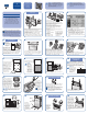
Push the
ejector
handles
inward to
lock the
controller
in place.
Repeat steps 17 through 19 for each controller to be
installed. Install 6U filler panels (slot covers) into all
unused slots.
Caution: Failure to install filler panels in unused
slots may result in thermal damage to the
hardware.
20 21 22
Tighten the captive screws to secure the controllers into
the expansion cage.
Push the ejector handles
so that they extend
towards the outer edges
of the Interface Manager
card.
Interface Manager
Card Installation
23 24
Push the ejector handles inward to lock the card in
place.
Align the sides of the Interface
Manager card with the guides
in either one of the 4U slots in
the expansion cage. Gently
push the Interface Manager
card into the expansion cage
slot, making sure that the
alignment pin on the card
aligns with the alignment hole
in the corresponding cage
slot. Push the card until the ejector handles engage the
metal rails on the top of the cage.
Note: If this is an upgrade installation, you will
need to remove a 4U filler panel before installing
the Interface Manager card.
25
If necessary, install a 4U filler panel (slot cover) into
the unused 4U slot.
Caution: Failure to install filler panels in
unused slots may result in thermal damage to
the hardware.
Tighten the captive screws to secure the Interface
Manager card into the expansion cage.
26
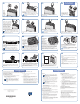
CASCADE TO FIBRE CHANNEL CONTROLLERS NETWORK SERIAL AUX STATUS
ERROR
27 28
Connect each of
the connectors
from the other end
of the Ethernet
cable bundle to
the Ethernet port
on the FC interface
controllers.
Note: The order in which the four Ethernet ports
labeled “To Fibre Channel Controllers” on the
Interface Manager card are connected to the FC
interface controllers is inconsequential. If less than four
FC interface controllers are installed, leave the unused
connectors from the Ethernet cable bundle hanging.
Connect the four connectors from one end of the
Ethernet cable bundle to the four Ethernet ports labeled
“To Fibre Channel Controllers” on the Interface
Manager card.
Note: Be sure to connect all four Ethernet
cables from the Ethernet cable bundle, even if
you are not using four FC interface controllers.
29 30
Connect the FC cables from any external fibre devices
to the FC connectors on the FC interface controllers.
Route the FC cables through the access port on the
back of the library.
Caution: Do not pinch the FC cables or bend
them in such a way that the radius of the bend
is less than two inches.
Connect the SCSI
connectors on the
FC interface
controllers to the SCSI
connectors on the
library SCSI
bulkhead. Refer to the
HP StorageWorks
Interface Manager
and Command View TL Installation Guide for detailed
SCSI cabling instructions. Secure the SCSI cables going
from the controller to the library bulkhead by snapping
them into the clips in the upper and lower cable clamps
located on the electronics enclosure. To prevent
interference with the door, do not use the fourth and fifth
clips from the right edge of the cable clamp.
CASCADE TO FIBRE CHANNEL CONTROLLERS NETWORK SERIAL AUX STATUS
ERROR
NETWORK SERIA
31
Connect a standard RJ-45 Ethernet cable from the LAN
to the Ethernet port labeled “Network” on the Interface
Manager card.
CASCADE TO FIBRE CHANNEL CONTROLLERS NETWORK SERIAL AUX STATUS
ERROR
CASCADE
32
To prepare for the configuration procedure, use a standard
RJ-45 network cable to connect the network port of the PC
or laptop to the port labeled "Cascade" on the Interface
Manager card. Route the cable through the access port on
the back of the library (see step 30).
33 34
Power on the ESL9000 Series library using the following
sequence:
a. Turn on both circuit breakers on the AC power
distribution assembly.
b. Verify that all access panels are closed, all back
panel cable connections are firmly in place, and all
doors are closed.
c. Turn on the power switch located below the control
panel.
After successfully installing the hardware, proceed to the
“Configuration” section.
Verify that filler panels are installed in all unused slots in
the expansion cage. Push the electronics bay back into
the library cabinet and finger-tighten the two captive
screws to secure the electronics bay in place.
For detailed configuration instructions, refer to Chapter 3, “Configuration and Software Installation,” of the
HP StorageWorks Interface Manager and Command View TL Installation Guide
Getting/Setting the IP Address
of the Interface Manager Card
1. Start a Telnet session on the PC or laptop that you connected
to the Interface Manager card in Step 32:
a. From a command prompt, enter the following:
telnet 192.168.2.1
Note: The above IP address is the IP address of the
cascade port. It is not the network IP address. The
cascade IP address is hardcoded into the Interface
Manager card and is separate from the network IP
address.
b. At the login prompt, use the following information:
• Username: cliadmin
• Password: clipwd
2. To display the current network IP address along with other
network information, enter the following command:
show network ipaddress
• If the IP address is 1.1.1.1, then DHCP mode was either
disabled, or unable to obtain an IP address automatically.
Proceed to Step 3 to set the IP address.
• If the IP address is anything other than 1.1.1.1, then
DHCP obtained the IP address automatically. If you choose
to keep this IP address, then record it and proceed to
Step 5. To change the address, continue with Step 3.
Configuration
© Copyright 2005 Hewlett-Packard Development Company, L.P.
Second Edition (March 2005)
Part Number: 341428-002
*341428-002*
341428-002
(continued)
Note: HP recommends using a static IP address
provided by your network administrator for the
Interface Manager card rather than an IP address
assigned by DHCP.
3. Obtain an IP address, subnet mask, and gateway address for
the Interface Manager card from your network administrator.
4. To change the IP address enter the following command
with all arguments: set network ipaddress
<IP
address> <subnet mask> <gateway address>
Note: The default gateway must be set to a valid
gateway address.
5. Use the exit command to end the Telnet session.
6. Disconnect the Ethernet cable from the Cascade port of the
Interface Manager card.
7. Using a 5/32 inch Allen wrench, close and secure the back
access door of the library.
Command View TL Prerequisites
For the server side, Command View TL requires a management
station (server) with a minimum of:
• Pentium III 500-MHz, 256-MB RAM
• 10/100 Base-T network card (a static IP address is recommended)
• Microsoft Windows 2000 Professional or Server edition SP3,
Windows XP Professional
For the client side, Command View TL requires the following:
• Microsoft Internet Explorer v6.0 SP1 or later, or Netscape
Navigator v6.2 or later. Make sure that Java support is
enabled in the browser
• An Internet connection is recommended to enable Command
View TL to receive firmware and software release information
automatically from the HP support website.
Starting Command View TL
1. Install the Command View TL software on the management
station.
a. Insert the Command View TL software CD into the
CD-ROM drive of the management station.
b. If autorun is disabled on the CD-ROM drive, locate and
double-click the setup.exe file on the CD.
c. Follow the instructions on the screen to complete the
installation.
d. Reboot the management station.
2. Open a supported browser on either the management station
or any computer on the LAN, and enter the following URL in
the address field: http://
<hostname>
:4095/ (where
<hostname> is the IP address or network name of the
management station. If you are opening a browser on the
management station itself, you can substitute localhost for
the hostname).
Configuring Command View TL
After installing the Interface Manager card and Command View TL,
you must perform the following configuration steps using
Command View TL:
• Set the Command View TL administrative password.
• Verify proxy settings for the management station.
• Add all libraries to Command View TL that will be monitored.
• Add the license key for Command View TL and any additional
features that you have purchased.
• Configure properties for each library.
• Configure host access (Secure Manager).
For complete instructions for each of these configuration steps, see
“Initial Configuration Steps” in Chapter 2 of the HP StorageWorks
Interface Manager and Command View TL User Guide.