System Installation Guide D Class and R Class HP 9000 Enterprise Servers Part No.
Legal Notices The information in this document is subject to change without notice. Hewlett-Packard makes no warranty of any kind with regard to this manual, including, but not limited to, the implied warranties of merchantability and fitness for a particular purpose. Hewlett-Packard shall not be held liable for errors contained herein or direct, indirect, special, incidental or consequential damages in connection with the furnishing, performance, or use of this material. Restricted Rights Legend.
Printing History The manual printing date and part number indicate its current edition. The printing date will change when a new edition is printed. Minor changes may be made at reprint without changing the printing date. The manual part number will change when extensive changes are made. Manual updates may be issued between editions to correct errors or document product changes. To ensure that you receive the updated or new editions, you should subscribe to the appropriate product support service.
Who Should Use this Guide The procedures in this guide are intended to be performed by a person who is qualified in the installation and servicing of computer equipment, and is trained to recognize the hazards involved. Internal add-on options cards are installed in an area of the product where energy levels which are considered hazardous may be produced.
Contents 1. D Class System Installation Overview of System Installation . . . . . . . . . . . . . . . . . . . . . . . . . . . . . . . . . . . . . . 1-2 1. Install Internal Add-on Options . . . . . . . . . . . . . . . . . . . . . . . . . . . . . . . . . . . . . 1-4 2. Connect the Console or Graphics Monitor . . . . . . . . . . . . . . . . . . . . . . . . . . . . 1-5 3. Connect the SCSI, Network, and Parallel Cables . . . . . . . . . . . . . . . . . . . . . . . 1-6 4.
Contents 6. Connect the System Power Cords . . . . . . . . . . . . . . . . . . . . . . . . . . . . . . . . . . 2-16 7. Turn On Power to the System . . . . . . . . . . . . . . . . . . . . . . . . . . . . . . . . . . . . . 2-18 8. Prepare for Network Connections . . . . . . . . . . . . . . . . . . . . . . . . . . . . . . . . . . 2-19 9. Prepare for Terminal Connections . . . . . . . . . . . . . . . . . . . . . . . . . . . . . . . . . . 2-20 Contacting Hewlett-Packard . . . . . . . . . . . . . . . . . . . . .
1 D Class System Installation How to install the basic HP 9000 D Class Enterprise server and its associated components, such as the console and keyboard.
D Class System Installation Overview of System Installation Overview of System Installation Installation of a basic system consists of the following procedures: 1. Install internal add-on options. 2. Connect the console or graphics monitor. 3. Connect the SCSI, network, and parallel cables. 4. Connect Remote Management (Access Port) card and the serial data cable for the optional UPS. 5. Set the input voltage selector. 6. Connect system power cords. 7. Turn on power to the system. 8.
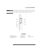
D Class System Installation Overview of System Installation CAUTION To avoid damage to the front panel of the server, DO NOT use any part of the front panel as a handle to lift or move the D Class server cabinet. When moving or lifting the server cabinet, be sure that the front panel peripheral door is locked. REAR PANEL CONNECTORS 1. Serial (D3xx servers) or Serial 2/UPS (D2xx servers) 2. SCSI (Single-Ended) 3. Graphics Mouse 4. LAN 10 Base-T 5. Serial 1/Console 6. Parallel 7.
D Class System Installation 1. Install Internal Add-on Options 1. Install Internal Add-on Options D Class servers are configured at the factory to include most I/O cards and internal peripherals. If you have any internal add-on options, install them now according to the instructions shipped with the option. WARNING DO NOT CONNECT SYSTEM POWER CORD AT THIS TIME.
D Class System Installation 2. Connect the Console or Graphics Monitor 2. Connect the Console or Graphics Monitor 1. Console/ Keyboard If you have an ASCII console (such as the HP 700/96) connect it to the server rear panel connector labeled Serial 1/ Console. Connect the keyboard to the keyboard connector at the rear of the console. 2. D3xx Graphics Monitor, Keyboard, Mouse If you have a D3xx server with a graphics monitor, connect it to the graphics I/O card at the rear of the system cabinet.
D Class System Installation 3. Connect the SCSI, Network, and Parallel Cables 3. Connect the SCSI, Network, and Parallel Cables 1. Connect your SCSI device cable to the connector labeled SCSI (Single-Ended) on the server rear panel. If no SCSI cable is to be attached to the server, place or leave the SCSI terminator (supplied with your server) on the SCSI (SingleEnded) connector. 2. Connect your parallel device, such as a printer, to the rear panel connector labeled Parallel. 3.
D Class System Installation 4. Connect Remote Management Card and Serial Data Cable for the Optional UPS 4. Connect Remote Management Card and Serial Data Cable for the Optional UPS The Remote Management card (also called the Access Port or AP card) is optional on Model D2xx servers, and standard on Model D3xx servers. The Remote Management card is located in different slots depending on which model of D Class server you have.
D Class System Installation 4. Connect Remote Management Card and Serial Data Cable for the Optional UPS Model D3xx 1. Connect your Line Access Module (LAM), for connecting to the phone line, to the Modem/LAM connector on the Remote Management (Access Port) card. 2. If you have a UPS, connect the UPS data cable from the UPS Port on the UPS to the UPS connector on the Remote Management card.
D Class System Installation 5. Set the Input Voltage Selector 5. Set the Input Voltage Selector CAUTION To avoid damage to your server, be sure to set the input voltage selector switch to a setting within the voltage range of the power source you intend to use. Always check the switch setting before connecting the power cord. 1. If your input voltage is in the range of 100 V to 127 V, set the voltage selector to the 115 setting. 2.
D Class System Installation 6. Connect the System Power Cords 6. Connect the System Power Cords How you connect the system power cords depends on whether your server configuration includes the optional Uninterruptible Power System (UPS). Be sure to connect power correctly for your system, as shown below. WARNING Be sure the server cabinet is closed and secured before connecting power cord. Refer to the WARNING on page 4.
D Class System Installation 6.
D Class System Installation 7. Turn On Power to the System 7. Turn On Power to the System 1. If you have the optional UPS, set the Power switch on the front panel of the UPS to the ON position. The green AC Output light should be on. If any of the other UPS front panel lights are on, refer to the UPS manual for appropriate action. 2. Turn on the system console (or graphics monitor). 3. Set the Power switch on the front panel of the D Class server to the ON position.
D Class System Installation 8. Prepare for Network Connections 8. Prepare for Network Connections To use your D Class server on a network, you will need the following information: • LAN station address (see system label) • System name (or hostname) • Internet Protocol (IP) address. The LAN station address is provided on the server’s system label located on the inside of the front panel peripheral door. Write the number down and give it to your system administrator.
D Class System Installation 9. Prepare for Terminal Connections 9. Prepare for Terminal Connections Configure your D Class server for terminal connections using the System Administration Manager (SAM) program. To use SAM, refer to the following manuals that were shipped with your system: • System Administration Tasks • Configuring HP-UX for Peripherals.
D Class System Installation 10. Contacting Hewlett-Packard 10. Contacting Hewlett-Packard If you need to contact Hewlett-Packard for assistance or additional information, you may be asked for the system model number and serial number. That information is located on the system label, on the back of the removable media access door. Reference Documents Refer to the following documents for additional information on using your HP 9000 D Class server: 1.
D Class System Installation 10.
2 R Class System Installation How to install the basic HP 9000 R Class Enterprise server and its associated components, such as the console and keyboard.
R Class System Installation Overview of System Installation Overview of System Installation Installation of a basic system consists of the following procedures: 1. If the server is not already integrated in a cabinet: a. Install the rack kit into a cabinet b. Mount the system on the cabinet rack 2. Install internal add-on options. 3. Connect the console, web console, or graphics monitor. 4. Connect the SCSI, network, and parallel cables. 5.
R Class System Installation 1. Install the Rack Kit and Server Into the Cabinet 1. Install the Rack Kit and Server Into the Cabinet If your R Class server has been factory integrated into a cabinet, or if you are going to operate the R Class server as a stand-alone unit, proceed to “2. Install Internal Add-on Options” on page 2-9. Otherwise, follow these instructions to install the rack kit onto your cabinet and mount the server onto the rack in the cabinet.
R Class System Installation 1. Install the Rack Kit and Server Into the Cabinet 1A. Install the Rack Kit 1. Decide where in the cabinet the new computer equipment is to be installed. R Class servers should be installed in the cabinet’s topmost available 6 EIA units On C2785A, C2786A, and C2787A cabinets, each EIA unit is marked by a triangular hole. On the J1501A, J1502A, and J1503A cabinets, these units are numbered. 2.
R Class System Installation 1. Install the Rack Kit and Server Into the Cabinet 6. Make sure the sheet metal nuts are aligned with the mounting holes in the rail. 7. Insert the M5x30mm mounting screws through the mounting holes on each rail, (through the spacers, if used), into the sheet metal nuts, and tighten. See the figures below for an example. The figure on the left shows installation without spacers. 8. Install the new piece of computer equipment. Slide it all the way into the cabinet. 9.
R Class System Installation 1. Install the Rack Kit and Server Into the Cabinet 10. Install the retaining screws (one for each clamp) into the mounting holes using the TORX screwdriver.
R Class System Installation 1. Install the Rack Kit and Server Into the Cabinet 1B. Mount the System Into the Cabinet Using two people, lift the server up and onto the rails in the cabinet. Slide the server toward the rear of the cabinet until the sheet metal extensions on the face of the server rest flush against the columns of the cabinet.
R Class System Installation 1. Install the Rack Kit and Server Into the Cabinet Attach the LCD and power switch bezel to the face of the server, then attach the front panel bezel. CAUTION Until the LCD and power switch bezel is attached, the area surrounding the LCD is ESD sensitive. See “Electrostatic Discharge Precautions” on page 2-3. In the rear of the cabinet, adjust the rail slide against the rear of server.
R Class System Installation 2. Install Internal Add-on Options 2. Install Internal Add-on Options WARNING The HP 9000 R Class Enterprise Server weighs about 38 kg (82 lbs). You must use two people to lift the R Class server cabinet. REAR PANEL CONNECTORS 1. Serial Connector 2. Serial 1/Console 3. Parallel 4. SCSI (Single-Ended) LAN 10 Base-T 5.Graphics Keyboard 6. Graphics Mouse 7. LAN 10 Base-T R Class servers are configured at the factory to include most I/O cards and internal peripherals.
R Class System Installation 2. Install Internal Add-on Options WARNING DO NOT CONNECT SYSTEM POWER CORD AT THIS TIME. If you open the system cabinet when power is connected, you will be exposed to high-energy (high-amperage) circuits and possible ejection of molten metal. Be sure to remove all rings, watches, and other jewelry from fingers, wrists, and arms before opening the system cabinet.
R Class System Installation 3. Connect the Console, Web Console, or Graphics Monitor 3. Connect the Console, Web Console, or Graphics Monitor 1. Console/ Keyboard If you have an ASCII console (such as the HP 700/96) connect it to the server rear panel connector labeled Serial 1/ Console. Connect the keyboard to the keyboard connector at the rear of the console. 2.
R Class System Installation 3. Connect the Console, Web Console, or Graphics Monitor 2. Remove the adhesive backing and attach the Velcro to the Remote Web Console in the areas shown: 3. Align the Velcro strips on the Remote Web Console with the strips on the inside of the server chassis and press together. Connect the web console to the RS-232 console port, using the cable (HP part number A5176-63002) provided.
R Class System Installation 3. Connect the Console, Web Console, or Graphics Monitor IMPORTANT POWER ADAPTORS FOR THE REMOTE WEB CONSOLE: The Remote Web Console, used with an R-Class server in either a racked or standalone configuration, receives power from a special power adaptor included with your shipment. The localized power adaptor included in the Remote Web Console box is qualified for use ONLY for stand-alone (non-racked) servers. Do not use this power adaptor for racked server solutions.
R Class System Installation 3. Connect the Console, Web Console, or Graphics Monitor 3. Graphics Monitor, Keyboard, Mouse If you have a graphics monitor, connect it to the graphics I/O card at the rear of the system cabinet. Connect the keyboard and mouse to the connectors labeled with keyboard and mouse symbols at the rear of the cabinet. The interface card for the graphics monitor can be installed in any open HP-HSC slot.
R Class System Installation 4. Connect the SCSI, Network, and Parallel Cables 4. Connect the SCSI, Network, and Parallel Cables 1. Connect your SCSI device cable to the connector labeled SCSI (Single-Ended) on the server rear panel. If no SCSI cable is to be attached to the server, place or leave the SCSI terminator (supplied with your server) on the SCSI (SingleEnded) connector. 2. Connect your parallel device, such as a printer, to the rear panel connector labeled Parallel. 3.
R Class System Installation 5. Connect Remote Management Card and Serial Data Cable for the Optional UPS 5. Connect Remote Management Card and Serial Data Cable for the Optional UPS R Class Servers The Remote Management card (also called the Access Port or AP card) is optional on R Class servers. When present, the AP card is always installed in slot 0. 1. Connect your Line Access Module (LAM), for connecting to the phone line, to the Modem/LAM connector on the Remote Management (Access Port) card. 2.
R Class System Installation 6. Connect the System Power Cords 6. Connect the System Power Cords How you connect the system power cords depends on whether your server configuration includes the optional Uninterruptible Power System (UPS). Be sure to connect power correctly for your system, as shown below. WARNING Be sure the server cabinet is closed and secured before connecting power cord. Refer to the WARNING on page 2-10.
R Class System Installation 6. Connect the System Power Cords sockets along the top of the UPS rear panel. Finally, connect your AC power source to the input socket of the UPS.
R Class System Installation 7. Turn On Power to the System 7. Turn On Power to the System 1. If you have the optional UPS, set the Power switch on the front panel of the UPS to the ON position. The green AC Output light should be on. If any of the other UPS front panel lights are on, refer to the UPS manual for appropriate action. 2. Turn on the system console or graphics monitor. 3. Set the Power switch on the front panel of the R Class server to the ON position.
R Class System Installation 8. Prepare for Network Connections 8. Prepare for Network Connections To use your R Class server on a network, you will need the following information: • LAN station address (see system label) • System name (or hostname) • Internet Protocol (IP) address. The LAN station address is provided on the server’s system label located on the inside of the front panel peripheral door. Write the number down and give it to your system administrator.
R Class System Installation 9. Prepare for Terminal Connections 9. Prepare for Terminal Connections Configure your R Class server for terminal connections using the System Administration Manager (SAM) program. To use SAM, refer to the following manuals that were shipped with your system: • System Administration Tasks • Configuring HP-UX for Peripherals.
R Class System Installation Contacting Hewlett-Packard Contacting Hewlett-Packard If you need to contact Hewlett-Packard for assistance or additional information, you may be asked for the system model number and serial number. That information is located on the system label, on the back of the removable media access door. Reference Documents Refer to the following documents for additional information on using your HP 9000 R Class server: 1.