HP ElitePad 1000 G2 Maintenance and Service Guide IMPORTANT! This document is intended for HP authorized service providers only.
© Copyright 2014 Hewlett-Packard Development Company, L.P. Bluetooth is a trademark owned by its proprietor and used by Hewlett-Packard Company under license. Intel is a U.S. registered trademark of Intel Corporation. Microsoft and Windows are U.S. registered trademarks of Microsoft Corporation. SD Logo is a trademark of its proprietor. The information contained herein is subject to change without notice.
Safety warning notice WARNING! To reduce the possibility of heat-related injuries or of overheating the device, do not place the device directly on your lap or obstruct the device air vents. Use the device only on a hard, flat surface. Do not allow another hard surface, such as an adjoining optional printer, or a soft surface, such as pillows or rugs or clothing, to block airflow. Also, do not allow the AC adapter to contact the skin or a soft surface, such as pillows or rugs or clothing, during operation.
iv Safety warning notice
Table of contents 1 Product description ........................................................................................................... 1 2 External component identification ..................................................................................... 4 Front ....................................................................................................................................... 4 Rear ........................................................................................
Display assembly .................................................................................................... 30 NFC antenna .......................................................................................................... 38 WWAN module ..................................................................................................... 39 WLAN module ........................................................................................................ 41 Microphones ....................
Determining the BIOS version .................................................................... 93 Downloading a BIOS Update ................................................................................... 93 Using HP PC Hardware Diagnostics (UEFI) ................................................................. 94 7 Specifications .................................................................................................................. 95 Tablet specifications ................................
viii
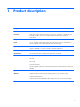
1 Product description Category Description Product Name HP ElitePad 1000 G2 Processor Intel® Atom z3795 1.60-GHz processor (core burst up to 2.39-GHz), 1.60-GHz front-side bus (FSB), 2.0-MB L2 cache, up to 778-MHz graphics burst frequency, soldered to system board Graphics Intel HD Graphics Panel 10.1-in.
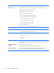
Category Description Wireless (continued) Integrated wireless wide area network (WWAN) options by way of wireless module Integrated world-wide/5-band WWAN antennas Secured by subscriber identity module (SIM) Support for the following WWAN formats: ● HP hs3110 HSPA+ Mobile Broadband Module ● HP lt4111 LTE/EV-DO/HSPA+ Gobi 4G Module ● HP lt4112 LTE/HSPA+ Gobi 4G Module ● HP lt4225 LTE/EV-DO Gobi 4G Module ● HP lt4226 LTE/HSPA+ Gobi 4G Module Support for no WWAN option Integrated near field commun
Category Description Security Support for trusted platform module (TPM; Infineon TPM is SLB9656VQ1.2FW4.32) Operating system Preinstalled: ● Microsoft® Windows® 8.1 ML 64-bit ● Microsoft Windows 8.1 EM 64-bit ● Microsoft Windows 8.1 CM 64-bit ● Microsoft Windows 8.1 Professional 64-bit ● Microsoft Windows 8.1 Professional 64-bit MSNA ● Microsoft Windows 8.1 Professional 64-bit Retail Solutions ● Microsoft Windows 8.1 SST 64-bit with Home and Student DPK ● Microsoft Windows 8.
2 External component identification Front Item Component Description (1) WWAN antennas (2)* (select models only) Send and receive wireless signals to communicate with WWANs. (2) Front webcam Records video and captures still photographs. To use the webcam, tap the YouCam tile on the Start screen, or swipe from the right edge of the touch screen to display the charms, tap Search, and then tap the search box. In the search box, type c, and then tap CyberLink YouCam.
Item Component Description (4) Ambient light sensor The ambient light sensor automatically adjusts the display brightness based on the lighting conditions in your environment. (5) Webcam status light (front) On: The webcam is on. (6) Near Field Communications (NFC) tapping area Allows you to touch an NFC-compatible device to this area to wirelessly connect and communicate with the tablet and transfer data back and forth. (7) Windows button Displays the Start screen.
Item Component Description (3) Rear webcam Records video, captures still photographs, and allows video conferences and online chat by means of streaming video. To use the webcam, tap the YouCam tile on the Start screen, or swipe from the right edge of the touch screen to display the charms, tap Search, and then tap the search box. In the search box, type c, and then tap CyberLink YouCam. (4) Volume up button To increase speaker volume, press the top edge of the button.
Item Component Description (2) Autorotate switch When the tablet is on, slide the autorotate switch to lock the autorotate feature of the display. To unlock the autorotate feature, slide the switch again. – or – Swipe from the right edge of the touch screen to display the charms, tap Settings, tap the screen icon, and then tap the autorotate icon. To unlock the autorotate feature, tap the autorotate icon again. (3) Integrated microphones (2) Record sound.
3 Illustrated parts catalog NOTE: HP continually improves and changes product parts. For complete and current information on supported parts for your computer, go to http://partsurfer.hp.com, select your country or region, and then follow the on-screen instructions. Service tag When ordering parts or requesting information, provide the tablet serial number and model number provided on the service tag.
Tablet major components Item Component Spare part number (1) Display assembly (10.1-in.
Item Component (4c) Autorotate switch actuator (4d) Slot cover hardware (slot cover, retention bracket, spring bracket) (4e) Docking connector bracket Webcam/Microphone Kit, includes: (5a) Left microphone (5b) Right microphone (6a) Rear-facing webcam (6b) Front-facing webcam (7) Power button board (includes cable) Spare part number 762828-001 For use only on tablet models equipped with the Windows 8 Professional operating system 753976-601 For use only on tablet models equipped with th
Item Component Spare part number (15) Broadcom BCM43241 802.11abgn 2x2 Wi-Fi + BT 4.
Retail Jacket components 12 Item Description Spare part number (1) Top cap (includes 4 captive screws, secured by C-rings) 744025-001 (2) Battery (2-cell, 21-Wh, 2.
Item Description Spare part number (8d) Credit card reader board/right board cable (9) Left-side credit card reader board 744027-001 (10) Right-side credit card reader board 744028-001 (11) Credit card reader (includes cable) 744026-001 (12) Battery connector board (includes cable) 744033-001 (13) System board (includes docking connector and USB port) 744032-001 (14) Rear cover 744029-001 Retail Jacket equipped with battery (not illustrated) 742441-001 Retail Jacket equipped with a
Security Jacket components 14 Item Description Spare part number (1) Top cap (includes rubber trim) 744047-001 (2) Card reader cover 744039-001 (3) Front cover 744048-001 (4) Rear cover (includes top cap release latch assembly) 744041-001 (5) Fingerprint reader board 744042-001 (6) Card reader board 744043-001 (7) System board 744044-001 Cables/Connectors Kit, includes: 744045-001 (8a) Fingerprint reader board cable (8b) Card reader board cable (8c) Docking connector cable S
Item Description Spare part number Rubber Kit for use only on the Security Jacket (not illustrated) 744040-001 Screw Kit for use only on the Security Jacket (not illustrated) 744046-001 Adapter cables Item Description Spare part number (1) HDMI/VGA adapter cable 695551-001 (2) Ethernet adapter cable 695555-001 (3) Serial adapter cable 695556-001 (4) HP Smart AC adapter cable 695553-001 (5) USB adapter cable 695552-001 (6) Card Reader adapter 695554-001 Adapter cables 15
Docking station and accessories 16 Item Description Spare part number (1) Docking station 708621-001 (2) 40-W HP Smart AC adapter (RC, V, 3-wire) 693717-001 (3) Power cord (3-pin, black, 1.
Item Description Spare part number For use in Taiwan 490371-AB1 For use in the United Kingdom and Singapore 490371-031 Miscellaneous parts Component Spare part number Carrying case: HP ElitePad dockable case 742720-001 HP ElitePad rugged carrying case 708772-001 HP ElitePad Service Tool (includes suction cup) 714222-001 HP ElitePad suction cup 714223-001 HP executive tablet pen 716117-001 Jacket: Slate jacket with battery slot (includes battery) 709462-001 Slate jacket without battery s
18 Component Spare part number For use in the Netherlands 724301-B31 For use in Norway 724301-091 For use in Northwest Africa 724301-FP1 For use in Portugal 724301-131 For use in Romania 724301-271 For use in Russia 724301-251 For use in Saudi Arabia 724301-171 For use in Slovenia 724301-BA1 For use in South Korea 724301-AD1 For use in Spain 724301-071 For use in Sweden and Finland 724301-B71 For use in Switzerland 724301-BG1 For use in Taiwan 724301-AB1 For use in Thailand 724
Power components Item Component Spare part number (1) 10-W AC adapter for use only on the HP ElitePad 1000 G2 (RC, V, 3-wire, wallmount) 686120-001 (2) Duck head power adapter: (3) For use in Argentina 755184-D01 For use in Australia 755184-011 For use in Brazil 755184-201 For use in Denmark 755184-081 For use in Europe 755184-021 For use in India 755184-D61 For use in Israel 755184-BB1 For use in Italy 755184-061 For use in the People's Republic of China 755184-371 For use in So
Item Component Spare part number For use in Europe 490371-021 For use in India 490371-D61 For use in Israel 490371-BB1 For use in Italy 490371-061 For use in Japan 490371-291 For use in North America 490371-001 For use in the People's Republic of China 490371-AA1 For use in South Africa 490371-AR1 For use in South Korea 490371-AD1 For use in Switzerland 490371-111 For use in Taiwan 490371-AB1 For use in the United Kingdom and Singapore 490371-031 Card Reader Cover Kit (not illustr
Spare part number Description 490371-BB1 Power cord for use in Israel (3-pin, black, 1.83-m) 490371-D01 Power cord for use in Argentina (3-pin, black, 1.83-m) 490371-D61 Power cord for use in India (3-pin, black, 1.83-m) 686120-001 10-W AC adapter (RC, V, 3-wire, wall-mount) 687946-001 2-cell, 21-Wh, 2.
22 Spare part number Description 724301-161 Jacket keyboard for use in Latin America 724301-171 Jacket keyboard for use in Saudi Arabia 724301-201 Jacket keyboard for use in Brazil 724301-211 Jacket keyboard for use in Hungary 724301-251 Jacket keyboard for use in Russia 724301-261 Jacket keyboard for use in Bulgaria 724301-271 Jacket keyboard for use in Romania 724301-281 Jacket keyboard for use in Thailand 724301-291 Jacket keyboard for use in Japan 724301-A41 Jacket keyboard for use
Spare part number Description 742442-001 Retail Jacket with battery bay space saver 742443-001 Retail Jacket Rubber Kit 742444-001 Security Jacket with screws 742446-001 Security Jacket with fingerprint reader and screws 742720-001 HP ElitePad dockable case 744025-001 Retail Jacket top cap (includes 4 captive screws, secured by C-rings) 744026-001 Retail Jacket credit card reader (includes cable) 744027-001 Retail Jacket left-side credit card reader board 744028-001 Retail Jacket right-si
24 Spare part number Description 747629-001 Speakers (include left and right speakers and cables 747630-001 Vibrator module (includes cable, double-sided adhesive, plastic cover) 747631-001 Docking connector cable (includes double-sided adhesive) 747632-001 Smart Card Reader Cover Kit 747633-001 NFC antenna (includes double-sided adhesive) 747634-001 Button Kit (includes autorotate switch actuator, docking connector bracket, power button actuator, slot cover hardware, and volume button actuato
Spare part number Description 755184-D61 Duck head power adapter for use only in India 756037-001 Security Jacket cover 759031-001 Volume button board (includes bracket and cable) 762827-001 Tape Support Kit 762828-001 Webcam/Microphone Kit (includes forward-facing and rear-facing webcams and microphones) 767882-001 3G antenna 767883-001 Antenna Kit for use only in the United States (includes WWAN/GPS auxiliary antenna cable and transceiver and WLAN main and auxiliary antenna cables and trans
4 Removal and replacement preliminary requirements Tools required You will need the following tools to complete the removal and replacement procedures: ● Magnetic screw driver ● Phillips P0 screw driver ● Plastic case utility tool Service considerations The following sections include some of the considerations that you must keep in mind during disassembly and assembly procedures.
Grounding guidelines Electrostatic discharge damage Electronic components are sensitive to electrostatic discharge (ESD). Circuitry design and structure determine the degree of sensitivity. Networks built into many integrated circuits provide some protection, but in many cases, ESD contains enough power to alter device parameters or melt silicon junctions. A discharge of static electricity from a finger or other conductor can destroy static-sensitive devices or microcircuitry.
Packaging and transporting guidelines Follow these grounding guidelines when packaging and transporting equipment: ● To avoid hand contact, transport products in static-safe tubes, bags, or boxes. ● Protect ESD-sensitive parts and assemblies with conductive or approved containers or packaging. ● Keep ESD-sensitive parts in their containers until the parts arrive at static-free workstations. ● Place items on a grounded surface before removing items from their containers.
Equipment guidelines Grounding equipment must include either a wrist strap or a foot strap at a grounded workstation. ● When seated, wear a wrist strap connected to a grounded system. Wrist straps are flexible straps with a minimum of one megohm ±10% resistance in the ground cords. To provide proper ground, wear a strap snugly against the skin at all times. On grounded mats with banana-plug connectors, use alligator clips to connect a wrist strap.
5 Removal and replacement procedures CAUTION: Components described in this chapter should only be accessed by an authorized service provider. Accessing these parts can damage the computer or void the warranty. NOTE: HP continually improves and changes product parts. For complete and current information on supported parts for your computer, go to http://partsurfer.hp.com, select your country or region, and then follow the on-screen instructions.
Remove the display assembly: 1. Remove the two Phillips PM1.4×3.2 screws that secure the display assembly to the tablet. 2. Place the HP ElitePad Service Tool on a flat, sturdy surface. The HP ElitePad Service Tool is available using spare part number 714222-001. 3. Move the HP ElitePad Service Tool retention bar (1) to the left until the notch (2) in the retention bar allows the retention gate to open.
32 4. Open the retention gate (3). 5. Place the tablet on the service tool and slide it (1) forward until the tablet docking connector engages with the service tool docking connector (2).
6. Close the retention gate (1) and release the retention bar (2) to secure the tablet in the service tool. 7. Place the suction cup (1) on the lower right corner of the tablet display glass, making sure to place the suction cup inside the edges of the border (2) of the display glass. The suction cup is available using spare part number 714223-001. 8. Raise the suction cup handle (3).
9. Lock the two suction cup handles together (4). CAUTION: Do not lift the right edge of the display assembly more than ¼-inch from the tablet when releasing the display assembly. Failure to follow this caution can result in damage to the tablet components. 10. Firmly lift up on the suction cup to release the right side of the display assembly approximately ¼inch from the tablet. 11. Move the retention bar (1) until the notch in the retention bar allows the retention gate to open.
12. Open the retention gate (2). 13. Slide the tablet out of the service tool (3). 14. Disconnect the suction cup handles (1). 15. Lower the suction cup handle (2). 16. Remove the suction cup (3). 17. Slide the display assembly (1) to the left until the display assembly cables and connectors are accessible. 18. Release the zero insertion force (ZIF) connector (2) to which the TouchScreen cable is attached, and then disconnect the TouchScreen cable (3) from the system board.
19. Release the ZIF connector (4) to which the LVDS cable is attached, and then disconnect the LVDS cable (5) from the system board. 20. Remove the display assembly and cables. 21. If it is necessary to replace the display assembly cables: 36 a. Turn the display assembly upside down, with the bottom toward you. b. Detach the TouchScreen cable (1) from the surface of the display assembly. (The TouchScreen cable is attached to the display assembly with double-sided adhesive.) c.
e. Release the ZIF connector (5) to which the display LVDS cable is attached, and then disconnect the display LVDS cable (6) from the display assembly. The TouchScreen and display LVDS cables are included in the Display Cable Kit, spare part number 718758-001. To install the display assembly: 1. Reconnect the display LVDS and TouchScreen cables to the respective ZIF connectors on the display assembly. 2.
NFC antenna Description Spare part number NFC antenna 747633-001 Before removing the NFC antenna, follow these steps: 1. Turn off the tablet. If you are unsure whether the tablet is off or in Hibernation, turn the tablet on, and then shut it down through the operating system. 2. Disconnect the power from the tablet by unplugging the power cord from the tablet. 3. Disconnect all external devices from the tablet. 4. Remove the display assembly (see Display assembly on page 30).
WWAN module Description Spare part number HP hs3110 HSPA+ Mobile Broadband Module 748599-005 HP lt4111 LTE/EV-DO/HSPA+ Gobi 4G Module 704030-005 HP lt4112 LTE/HSPA+ Gobi 4G Module 740011-005 HP lt4225 LTE/EV-DO Gobi 4G Module 736676-005 HP lt4226 LTE/HSPA+ Gobi 4G Module 736675-005 Before removing the WWAN module, follow these steps: 1. Turn off the tablet. If you are unsure whether the tablet is off or in Hibernation, turn the tablet on, and then shut it down through the operating system. 2.
4. Remove the WWAN module (4) by sliding it away from the socket on the system board. NOTE: If the WWAN antenna cables are not connected to the terminals on the WWAN module, protective sleeves should be installed on the antenna connectors, as shown in the following illustration. Reverse this procedure to install the WWAN module.
WLAN module Description Spare part number Broadcom BCM43241 802.11abgn 2x2 Wi-Fi + BT 4.0 Combo Adapter 723677-005 Before removing the WLAN module, follow these steps: 1. Turn off the tablet. If you are unsure whether the tablet is off or in Hibernation, turn the tablet on, and then shut it down through the operating system. 2. Disconnect the power from the tablet by unplugging the power cord from the tablet. 3. Disconnect all external devices from the tablet. 4.
5. Remove the WLAN module (5). NOTE: If the WLAN antenna cables are not connected to the terminals on the WLAN module, protective sleeves should be installed on the antenna connectors, as shown in the following illustration. Reverse this procedure to install the WLAN module.
Microphones NOTE: The microphones are included in the Webcam/Microphone Kit, spare part number 762828-001. Before removing the microphones, follow these steps: 1. Turn off the tablet. If you are unsure whether the tablet is off or in Hibernation, turn the tablet on, and then shut it down through the operating system. 2. Disconnect the power from the tablet by unplugging the power cord from the tablet. 3. Disconnect all external devices from the tablet. 4.
Rear-facing webcam NOTE: The rear-facing webcam is included in the Webcam/Microphone Kit, spare part number 762828-001. Before removing the rear-facing webcam, follow these steps: 1. Turn off the tablet. If you are unsure whether the tablet is off or in Hibernation, turn the tablet on, and then shut it down through the operating system. 2. Disconnect the power from the tablet by unplugging the power cord from the tablet. 3. Disconnect all external devices from the tablet. 4.
Power button board Description Spare part number For use only on computer models equipped with the Windows 8 Professional operating system 753976-601 For use only on computer models equipped with the Windows 8 Standard operating system 753976-501 For use only on computer models equipped with a non-Windows 8 operating system 753976-001 Before removing the power button board, follow these steps: 1. Turn off the tablet.
5. Detach the power button board cable (5) from the surface of the battery. (The power button board cable is attached to the battery with double-sided adhesive.) 6. Remove the Phillips PM1.3×2.0 broad head screw (1) and the Phillips PM1.3×2.0 screw (2) that secure the power button board to the bottom cover. 7. Remove the power button board (3) and cable. NOTE: In the process of removing the power button board, the power button actuator may be accidentally dislodged from the bottom cover.
Reverse this procedure to install the power button board. Volume button board Description Spare part number Volume button board (includes bracket and cable) 759031-001 Before removing the volume button board, follow these steps: 1. Turn off the tablet. If you are unsure whether the tablet is off or in Hibernation, turn the tablet on, and then shut it down through the operating system. 2. Disconnect the power from the tablet by unplugging the power cord from the tablet. 3.
4. Remove the volume button board (4) and cable. NOTE: In the process of removing the volume button board, the volume button actuator may be accidentally dislodged from the bottom cover. To replace the volume button actuator, refer to the following illustration. The volume button actuator is included in the Button Kit, spare part number 747634-001. Reverse this procedure to install the volume button board.
Audio jack board Description Spare part number Audio jack board (includes audio jack and cable) 747627-001 Before removing the audio jack board, follow these steps: 1. Turn off the tablet. If you are unsure whether the tablet is off or in Hibernation, turn the tablet on, and then shut it down through the operating system. 2. Disconnect the power from the tablet by unplugging the power cord from the tablet. 3. Disconnect all external devices from the tablet. 4.
Vibrator module Description Spare part number Vibrator module (includes cable, double-sided adhesive, plastic cover) 747630-001 Before removing the vibrator module, follow these steps: 1. Turn off the tablet. If you are unsure whether the tablet is off or in Hibernation, turn the tablet on, and then shut it down through the operating system. 2. Disconnect the power from the tablet by unplugging the power cord from the tablet. 3. Disconnect all external devices from the tablet. 4.
2. Detach the vibrator module (2) from the bottom cover. (The vibrator module is attached to the bottom cover with double-sided adhesive.) 3. Remove the vibrator module and cable. NOTE: The vibrator module cover is attached to the vibrator module with double-sided adhesive. Reverse this procedure to install the vibrator module. Battery Description Spare part number 2-cell, 30-Wh, 4.
5. Remove the NFC antenna (see NFC antenna on page 38). 6. Remove the power button board (see Power button board on page 45). Remove the battery: 1. Release the volume button board cable from the retention clips (1) built into the battery. 2. Release the tab (2) built into the bottom cover that secures the WWAN/GPS antenna cables, and then release the antenna cables (3). 3. Detach the WWAN/GPS main transceiver (4) from the bottom cover.
System board NOTE: The system board spare part kit is equipped with an Intel Atom z3795 quad core 1.60-GHz processor (burst up to 2.39-GHz; 2.0-MB L2 cache), and 4096-MB of system memory and includes the processor, memory, and eMMC. Description Spare part number Equipped with 128-GB of eMMC primary storage 753741-001 Equipped with 64-GB of eMMC primary storage 753740-001 Before removing the system board, follow these steps: 1. Turn off the tablet.
3. 54 Release the ZIF connector (3) to which the WLAN ribbon cable is attached, and then disconnect the WLAN ribbon cable from the WLAN module.
4. Remove the five Phillips PM1.3×2.0 screws that secure the battery to the bottom cover. 5. Lift the top edge of the system board (1) and swing it up and forward until it rests upside down above the tablet. 6. Remove the two Phillips PM1.3×1.5 broad head screws (2) that secure the docking connector cable to the system board.
7. Disconnect the docking connector cable (3) from the system board. 8. Remove the system board. NOTE: In the process of removing the system board, the autorotate switch actuator may be accidentally dislodged from the bottom cover. To replace the autorotate switch actuator, refer to the following illustration. When installing the autorotate switch actuator, make sure the two tabs (1) on the autorotate switch actuator engage the autorotate switch (2) on the system board.
Reverse this procedure to install the system board. Forward-facing webcam NOTE: The forward-facing webcam is included in the Webcam/Microphone Kit, spare part number 762828-001. Before removing the forward-facing webcam, follow these steps: 1. Turn off the tablet. If you are unsure whether the tablet is off or in Hibernation, turn the tablet on, and then shut it down through the operating system. 2. Disconnect the power from the tablet by unplugging the power cord from the tablet. 3.
2. Release the ZIF connector (1) to which the forward-facing webcam cable is attached, and then disconnect the forward-facing webcam cable (2) from the system board. 3. Remove the forward-facing webcam and cable. Reverse this procedure to install the forward-facing webcam. Slot cover NOTE: The slot cover is included in the Button Kit, spare part number 747634-001. Before removing the slot cover, follow these steps: 1. Turn off the tablet.
3. Remove the slot cover (4) by pressing it through the bottom cover. 4. Remove the slot cover. Reverse this procedure to install the slot cover. Docking connector cable Description Spare part number Docking connector cable (includes double-sided adhesive) 747631-001 Before removing the docking connector cable, follow these steps: 1. Turn off the tablet. If you are unsure whether the tablet is off or in Hibernation, turn the tablet on, and then shut it down through the operating system. 2.
d. Battery (see Battery on page 51) e. System board (see System board on page 53) Remove the docking connector cable: 1. Disconnect the vibrator module cable (1) from the docking connector cable. 2. Disconnect the speaker cable (2) from the docking connector cable. 3. Remove the two Phillips PM1.3×2.0 screws (3) that secure the docking connector cable bracket to the bottom cover. 4. Remove the docking connector bracket (4).
7. Remove the docking connector cable (3). Reverse this procedure to install the docking connector cable. WLAN antenna NOTE: The WLAN antenna are included in the Antenna Kits and include the WLAN antenna main and auxiliary cables and transceivers.
d. Battery (see Battery on page 51) e. System board (see System board on page 53) Remove the WLAN antenna: 1. Release the WLAN antenna cables from the routing channel (1) built into the bottom cover. 2. Detach the WLAN antenna transceivers (2) from the bottom cover. 3. Release the tabs (3) built into the bottom cover that secure the speaker cable, and then release the WLAN antenna cables. 4. Remove the WLAN antenna cables and transceivers (4). Reverse this procedure to install the WLAN antenna.
WWAN/GPS auxiliary antenna NOTE: The WWAN/GPS auxiliary antenna are included in the Antenna Kits and include the WWAN/GPS auxiliary antenna cable and transceiver. Description Spare part number Antenna Kit for use only in European countries and regions 767884-001 Antenna Kit for use only in Japan 767885-001 Antenna Kit for use only in the United States 767883-001 Before removing the WWAN/GPS auxiliary antenna, follow these steps: 1. Turn off the tablet.
2. Remove the WWAN/GPS auxiliary antenna cable and transceiver (2). Reverse this procedure to install the WWAN/GPS auxiliary antenna.
Speakers Description Spare part number Speakers (include left and right speakers and cables) 747629-001 Before removing the speakers, follow these steps: 1. Turn off the tablet. If you are unsure whether the tablet is off or in Hibernation, turn the tablet on, and then shut it down through the operating system. 2. Disconnect the power from the tablet by unplugging the power cord from the tablet. 3. Disconnect all external devices from the tablet. 4.
3. Remove the speakers (3). Reverse this procedure to install the speakers.
Retail Jacket component replacement procedures There are as many as 31 screws that must be removed, replaced, and/or loosened when servicing the Retail Jacket. Make special note of each screw size and location during removal and replacement. Top cap Description Spare part number Top cap (includes 4 captive screws, secured by C-rings) 744025-001 Before disassembling the Retail Jacket, follow these steps: 1. Turn off the tablet.
5. If installed, slide the tablet out of the Retail Jacket. Reverse this procedure to install the top cap. Battery Description Spare part number Battery (2-cell, 21-Wh, 2.96-Ah, Li-ion) 687946-001 Before removing the battery, follow these steps: 1. Turn off the tablet. If you are unsure whether the tablet is off or in Hibernation, turn the tablet on, and then shut it down through the operating system. 2.
2. Remove the battery (2) from the Retail Jacket. Reverse this procedure to install the battery. Front cover Description Spare part number Front cover (includes bar code scanner lens and adhesive liner) 744030-001 Before removing the front cover, follow these steps: 1. Turn off the tablet. If you are unsure whether the tablet is off or in Hibernation, turn the tablet on, and then shut it down through the operating system. 2.
Remove the front cover: 70 1. Position the Retail Jacket with the top toward you. 2. Remove the adhesive-backed liner that covers the front cover. 3. Release the ZIF connector (1) to which the left-side credit card reader board cable is attached, and then disconnect the left-side credit card reader board cable (2) from the left-side credit card reader board.
4. Close the ZIF connector (3). CAUTION: Failure to close the ZIF connector as instructed in step 4 can lead to damage to Retail Jacket components. 5. Position the Retail Jacket with the bottom toward you.
72 6. Remove the two Phillips PM1.3×3.0 screws that secure the front cover to the Retail Jacket. 7. Position the Retail Jacket with the top toward you. 8. Remove the four Phillips PM1.9×3.0 screws that secure the front cover to the Retail Jacket.
9. Remove the front cover by sliding it away from the Retail Jacket. Reverse this procedure to install the front cover. Bar code scanner module and Cable connector board NOTE: The bar code scanner module and cable connector board spare part kits do not include the respective cables. The cables are included in the Cable Kit, spare part number 744031-001.
74 3. Detach the cable connector board cable (2) from the front cover. (The cable connector board cable is attached to the front cover with double-sided adhesive.) 4. Remove the two Phillips PM1.3×3.0 screws (3) that secure the bar code scanner module to the front cover. 5. Remove the two Phillips PM1.9×3.0 screws (4) that secure the cable connector board to the front cover. 6. Remove the bar code scanner module (5) and the cable connector board and cable. 7.
8. Release the ZIF connector (1) to which the bar code scanner module cable is attached, and then disconnect the bar code scanner module cable (2) from the cable connector board. Reverse this procedure to install the bar code scanner module and cable connector board. Battery connector board Description Spare part number Battery connector board (includes cable) 744033-001 Before removing the battery connector board, follow these steps: 1. Turn off the tablet.
4. Lift the bottom edge of the battery connector board (3) until the board rests at an angle, and then slide the board out of the opening in the front cover. 5. Remove the battery connector board and cable. Reverse this procedure to install the battery connector board. System board Description Spare part number System board (includes docking connector and USB port) 744032-001 Before removing the system board, follow these steps: 76 1. Turn off the tablet.
Remove the system board: 1. Turn the front cover upside down with the top toward you. 2. Disconnect the battery connector board cable (1) from the system board. 3. Release the ZIF connector (2) to which the cable connector board cable is attached, and then disconnect the cable connector board cable from the system board. 4. Release the ZIF connector (3) to which the credit card reader/left board cable is attached, and then disconnect the credit card reader/left board cable from the system board. 5.
Credit card reader board NOTE: The credit card reader board spare part kits do not include the respective cables. The cables are included in the Cable Kit, spare part number 744031-001. Description Spare part number Left-side credit card reader board 744027-001 Right-side credit card reader board 744028-001 Before removing the credit card reader boards, follow these steps: 1. Turn off the tablet.
3. Release the ZIF connector (3) to which the right-side credit card reader board cable is attached, and then disconnect the right-side credit card reader board cable (4) from the left-side credit card reader board. 4. Remove the left-side credit card reader board. 5. Detach the right-side credit card reader board cable (1) from the rear cover. (The right-side credit card reader board cable is attached to the rear cover with double-sided adhesive.) 6. Remove the Phillips PM1.9×3.
7. Remove the right-side credit card reader board (3) and cable. Reverse this procedure to install the credit card reader boards. Credit card reader Description Spare part number Credit card reader 744026-001 Before removing the credit card reader, follow these steps: 1. Turn off the tablet. If you are unsure whether the tablet is off or in Hibernation, turn the tablet on, and then shut it down through the operating system. 2.
5. Remove the credit card reader (5). Reverse this procedure to install the credit card reader.
Security Jacket component replacement procedures There are as many as 13 screws that must be removed, replaced, and/or loosened when servicing the Security Jacket. Make special note of each screw size and location during removal and replacement. Card reader cover and Top cap Description Spare part number Card reader cover 744039-001 Top cap (includes rubber trim) 744047-001 Before disassembling the Security Jacket, follow these steps: 1. Turn off the tablet.
6. Remove the top cap (3) from the Security Jacket. CAUTION: Before positioning the Security Jacket with the tablet display panel facing down, make sure the work surface is clear of tools, screws, and any other foreign objects. Failure to follow this caution can result in damage to the display panel. 7. Turn the Security Jacket right side up with the bottom toward you. 8. If installed, slide the tablet out of the Security Jacket. Reverse this procedure to install the top cap.
Front cover Description Spare part number Front cover 744048-001 Before removing the front cover, follow these steps: 1. Turn off the tablet. If you are unsure whether the tablet is off or in Hibernation, turn the tablet on, and then shut it down through the operating system. 2. Disconnect the power from the tablet by unplugging the power cord from the tablet or the Security Jacket. 3. Disconnect all external devices from the Security Jacket. 4.
4. Remove the two Phillips PM1.3×3.4 screws (1) that secure the front cover to the Security Jacket. 5. Release the front cover (2) by sliding it partially away from the Security Jacket. 6. Lift the bottom edge of the front cover (1) and swing it up and back until it rests upside down on the Security Jacket. 7. Disconnect the fingerprint reader board cable (2) from the low insertion force (LIF) connector on the system board. 8.
System board Description Spare part number System board (includes docking connector, HDMI port, and USB port) 744044-001 Before removing the system board, follow these steps: 1. Turn off the tablet. If you are unsure whether the tablet is off or in Hibernation, turn the tablet on, and then shut it down through the operating system. 2. Disconnect the power from the tablet by unplugging the power cord from the tablet or the Security Jacket. 3. Disconnect all external devices from the Security Jacket.
Docking connector cable NOTE: The docking connector cable is included in the Cables/Connectors Kit, spare part number 744045-001. Before removing the docking connector cable, follow these steps: 1. Turn off the tablet. If you are unsure whether the tablet is off or in Hibernation, turn the tablet on, and then shut it down through the operating system. 2. Disconnect the power from the tablet by unplugging the power cord from the tablet or the Security Jacket. 3.
4. Remove the docking connector cable (3). Reverse this procedure to install the docking connector cable. Card reader board Description Spare part number Card reader board 744043-001 Before removing the card reader board, follow these steps: 88 1. Turn off the tablet. If you are unsure whether the tablet is off or in Hibernation, turn the tablet on, and then shut it down through the operating system. 2.
Remove the card reader board: 1. Position the rear cover with the bottom toward you. 2. Detach the tape (1) that secures the card reader board to the rear cover. 3. Remove the card reader board (2) and cable. Reverse this procedure to install the card reader board. Fingerprint reader board Description Spare part number Fingerprint reader board 744042-001 Before removing the fingerprint reader board, follow these steps: 1. Turn off the tablet.
Remove the fingerprint reader board: 1. Position the rear cover with the bottom toward you. 2. Remove the spring (1) from the spring retention tabs (2). 3. Remove the fingerprint reader board (3) and cable. Reverse this procedure to install the fingerprint reader board.
6 Computer Setup and HP PC Hardware Diagnostics (UEFI) Using Computer Setup Computer Setup, or F10 BIOS Setup (Basic Input/Output System), controls communication between all the input and output devices on the system (such as disk drives, display, keyboard, mouse, and printer). Computer Setup includes settings for the types of devices installed, the startup sequence of the tablet, and the amount of system and extended memory. NOTE: Use extreme care when making changes in Computer Setup.
Navigating and selecting in Computer Setup To navigate and select in Computer Setup, follow these steps: 1. Shut down the tablet. 2. To power on the tablet, press the Power button and Volume down button simultaneously. The Startup menu is displayed. 3. Press f10 to enter Computer Setup. ● Tap a menu or a menu item to select it. ● To close open dialog boxes and return to the main Computer Setup screen, tap Escape, and then follow the on-screen instructions. 4.
Updating the BIOS Updated versions of the BIOS may be available on the HP website. Most BIOS updates on the HP website are packaged in compressed files called SoftPaqs. Some download packages contain a file named Readme.txt, which contains information regarding installing and troubleshooting the file.
3. Follow the on-screen instructions. 4. At the download area, follow these steps: a. Identify the most recent BIOS update and compare it to the BIOS version currently installed on your tablet. Make a note of the date, name, or other identifier. You may need this information to locate the update later, after it has been downloaded to your hard drive. b. Follow the on-screen instructions to download your selection to the hard drive.
7 Specifications Tablet specifications Metric U.S. Width 17.80 cm 7.0 in Depth 26.10 cm 10.28 in Height 0.92 cm 0.36 in Weight 0.68 kg 1.50 lbs Dimensions Input power Operating voltage and current 9 V DC @ 1.
8 Backup and recovery To protect your information, use Windows backup and restore utilities to back up individual files and folders, back up your entire hard drive, create system repair media (select models only) by using an optional external flash drive, or an optional external optical drive, or create system restore points. In case of system failure, you can use the backup files to restore the contents of your tablet. 1.
Performing a system recovery In case of system failure or instability, the computer provides the following tools to recover your files: ● Windows recovery tools: You can use Windows Backup and Restore to recover information you have previously backed up. You can also use Windows Automatic Repair to fix problems that might prevent Windows from starting correctly. ● f11 recovery tools: You can use the f11 recovery tools to recover your original hard drive image.
Using f11 recovery tools CAUTION: Using f11 completely erases hard drive contents and reformats the hard drive. All files that you have created and any software that you have installed on the tablet are permanently removed. The f11 recovery tool reinstalls the operating system, drivers, Windows updates, and language packs that were installed at the factory. All other software applications must be downloaded from HP.com or the Windows Store.
Using Windows Refresh or Windows Reset When your tablet is not working properly and you need to regain system stability, the Windows Refresh option allows you to start fresh and keep what is important to you. The Windows Reset option allows you to perform detailed reformatting of your tablet, or remove personal information before you give away or recycle your tablet. For more information on these features, see Windows Help and Support.
9 Statement of Volatility The purpose of this document is to provide general information regarding non-volatile memory in industry-standards based HP Business Notebook PC systems and provide general instructions for restoring nonvolatile memory that can contain personal data after the system has been powered off and the hard drive has been removed. HP Business Notebook PC products that use Intel-based or AMD®-based system boards contain volatile DDR memory.
f. If an Automatic DriveLock password is set, select the Security menu, scroll down to Automatic DriveLock, then select the desired hard drive and disable protection. Repeat this procedure if more than one hard drive has an Automatic DriveLock password. g. Select the File menu, then Reset BIOS Security to factory default. Click yes at the warning message. h. Select the File menu, then Save Changes and Exit. i. Reboot the system.
Non-volatile memory usage 102 Non Volatile Memory Type Amount (Size) Does this memory store customer data? Does this memory retain data when power is removed? What is the purpose of this memory? How is data input into this memory? How is this memory write protected? Real Time Clock (RTC) battery backed-up CMOS configuration memory (CMOS) 256 Bytes No Yes Stores system date and time and limited keyboard controller data.
Non Volatile Memory Type Amount (Size) Does this memory store customer data? Does this memory retain data when power is removed? What is the purpose of this memory? How is data input into this memory? How is this memory write protected? System BIOS 4 to 5 MBytes Yes Yes Store system BIOS code and PC configuration data. System BIOS code is programmed at the factory. Code is updated when the system BIOS is updated.
104 Non Volatile Memory Type Amount (Size) Does this memory store customer data? Does this memory retain data when power is removed? What is the purpose of this memory? How is data input into this memory? How is this memory write protected? Bluetooth flash 2 MBits No Yes Stores Bluetooth configuration and firmware. Programmed at the factory. Tools for writing data to this memory are not publicly available but can be obtained from the silicon vendor.
Questions and answers 1. 2. How can the BIOS settings be restored (returned to default settings)? a. Turn on or restart the computer and press F10 when prompted near the bottom of the display. b. Select File, then select Restore defaults. c. Follow the on-screen instructions. d. Select File, save changes and exit, then press Enter.
10 Power cord set requirements The wide-range input feature of the computer permits it to operate from any line voltage from 100 to 120 volts AC, or from 220 to 240 volts AC. The 3-conductor power cord set included with the computer meets the requirements for use in the country or region where the equipment is purchased. Power cord sets for use in other countries and regions must meet the requirements of the country or region where the computer is used.
Requirements for specific countries and regions Country/region Accredited agency Applicable note number Australia EANSW 1 Austria OVE 1 Belgium CEBC 1 Canada CSA 2 Denmark DEMKO 1 Finland FIMKO 1 France UTE 1 Germany VDE 1 Italy IMQ 1 Japan METI 3 The Netherlands KEMA 1 Norway NEMKO 1 The People's Republic of China COC 5 South Korea EK 4 Sweden SEMKO 1 Switzerland SEV 1 Taiwan BSMI 4 The United Kingdom BSI 1 The United States UL 2 1.
11 Recycling When a non-rechargeable or rechargeable battery has reached the end of its useful life, do not dispose of the battery in general household waste. Follow the local laws and regulations in your area for battery disposal. HP encourages customers to recycle used electronic hardware, HP original print cartridges, and rechargeable batteries. For more information about recycling programs, see the HP Web site at http://www.hp.com/recycle.
Index Symbols/Numerics 3G antenna, spare part number 25 A AC adapter cable, spare part number 15, 21 AC adapter, spare part numbers 16, 19, 21 adapter cables illustrated 15 spare part numbers 15 adhesive cover spare part number 12 ambient light sensor 5 antenna location 4 removal 61, 63 spare part numbers 10, 25, 61, 63 Antenna Kit, spare part numbers 10, 25, 61, 63 audio jack board removal 49 spare part number 10, 23, 49 audio, product description 1 audio-in jack 6 audio-out jack 6 autorotate switch actua
docking connector cable removal 59, 87 spare part numbers 11, 24, 59, 87 docking station illustrated 16 spare part number 16, 21 docking, product description 2 duck head power adapter illustrated 19 spare part numbers 19, 24, 25 E electrostatic discharge 27 equipment guidelines 29 Ethernet adapter cable, spare part number 15, 21 Ethernet, product description 1 F fingerprint reader spare part number 23 fingerprint reader board removal 89 spare part number 14, 89 forward-facing webcam removal 57 spare part nu
R rear components 5 rear cover, spare part numbers 13, 14, 23 rear-facing webcam removal 44 spare part number 44 regulatory information 6, 7 removal/replacement procedures 30 Retail Jacket, spare part numbers 13, 22, 23 Rubber Kit, spare part numbers 13, 15, 23 S Screw Kit, spare part numbers 13, 15, 18, 20, 23, 24 Security Jacket, spare part numbers 14, 23 security, product description 3 sensors, product description 2 serial adapter cable, spare part number 15, 21 service considerations cables 26 connector