
Reference Guide
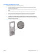
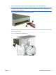
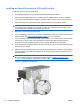
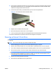
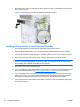
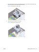
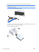
Table Of Contents
- Hardware Upgrades
- Warnings and Cautions
- Additional Information
- Removing the Computer Access Panel
- Replacing the Computer Access Panel
- Removing the Front Bezel
- Removing Bezel Blanks
- Replacing the Front Bezel
- Installing Additional Memory
- Removing or Installing an Expansion Card
- Drive Positions
- Installing Additional Drives
- Battery Replacement
- Installing a Security Lock
- Electrostatic Discharge
- Computer Operating Guidelines, Routine Care and Shipping Preparation
- Index
Installing an Optical Drive into the 5.25-inch Drive Bay
To install an optional 5.25-inch optical drive:
1. Remove/disengage any security devices that prohibit opening the computer.
2. Remove all removable media, such as compact discs or USB flash drives, from the computer.
3. Turn off the computer properly through the operating system, then turn off any external devices.
4. Disconnect the power cord from the power outlet and disconnect any external devices.
CAUTION: Regardless of the power-on state, voltage is always present on the system board as
long as the system is plugged into an active AC outlet. You must disconnect the power cord to
avoid damage to the internal components of the computer.
5. Remove the access panel and front bezel.
6. If you are installing a drive in a bay covered by a bezel blank, remove the front bezel then remove
the bezel blank. See
Removing Bezel Blanks on page 5 for more information.
7. If you are adding a drive to an empty lower optical drive bay, you must remove the knockout plate
from the bay. To do so, insert a flat screwdriver into the knockout plate slot and rotate the
screwdriver to break the knockout plate out of the chassis. Discard the knockout plate.
8. If the new drive has screws installed on the sides of the drive, remove the screws before inserting
the drive into the chassis.
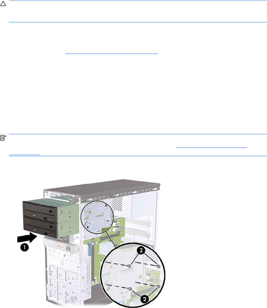
9. Slide the drive in through the front of the chassis (1) until the bezel on the drive is evenly aligned
with the computer front bezel and install the two M3 metric retainer screws (2) as shown in the
illustration below.
NOTE: Extra drive retainer screws are provided on the interior of the front bezel if needed. The
M3 metric retainer screws for optical drives are black. Refer to
Installing Additional Drives
on page 15 for an illustration of the retainer screws location.
Figure 17 Installing the Optical Drive
18 Hardware Upgrades ENWW